|
|
     aHR0cDovL2ZyZWVzaGlwLmNvLmty aHR0cDovL2ZyZWVzaGlwLmNvLmty
- 스마트 기기: no
- 신청: 선반 터닝 센터
- 모델 번호: DDCSV3.1 kit
- 근원: CN (정품)
packing list: 1 xDDC3.1 offline controller (3-axis and 4-axis optional)
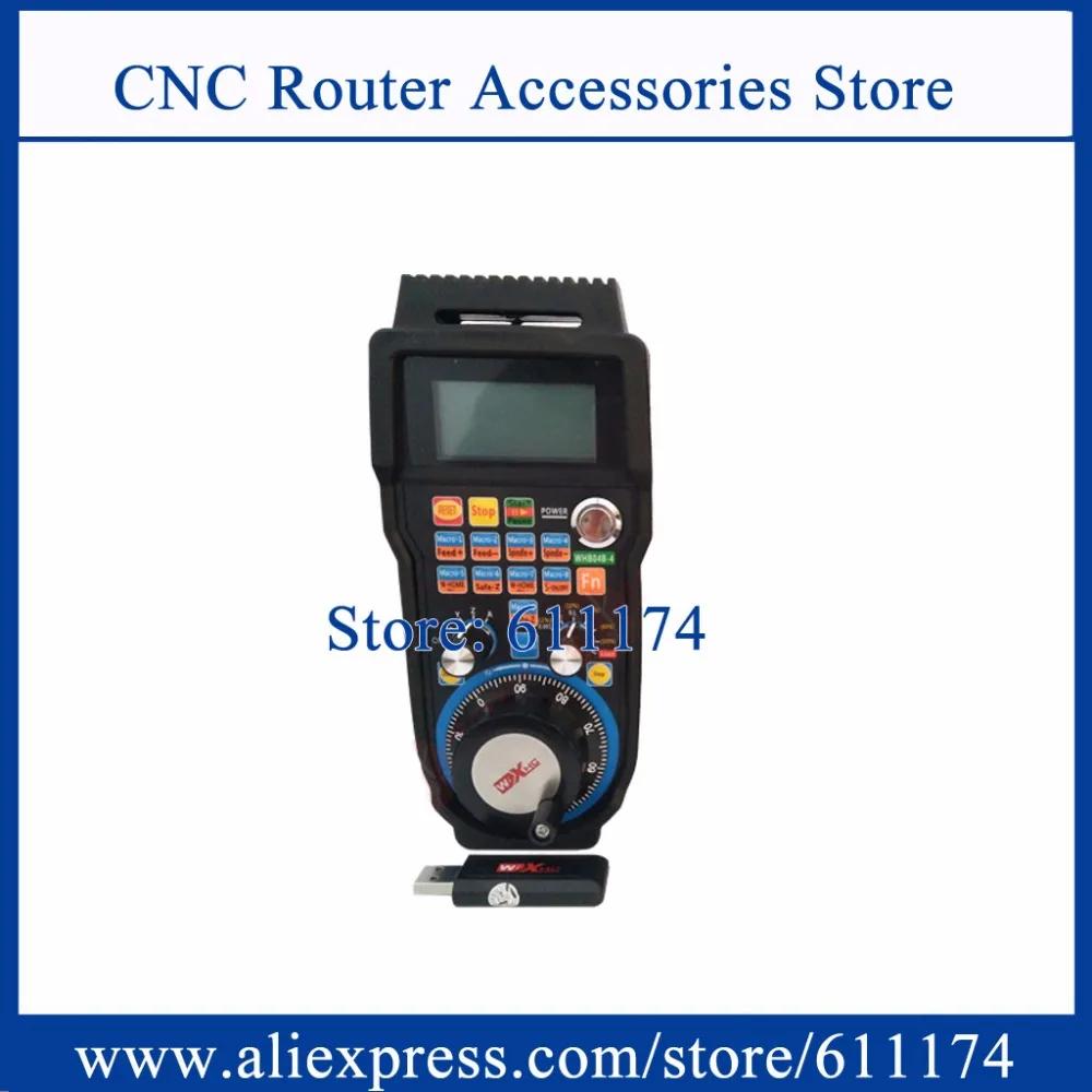
1 x Electronic handwheel with emergency stop
1 xDDC3.1 some small accessories
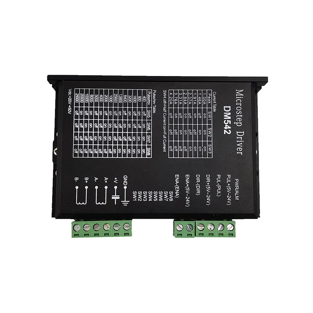
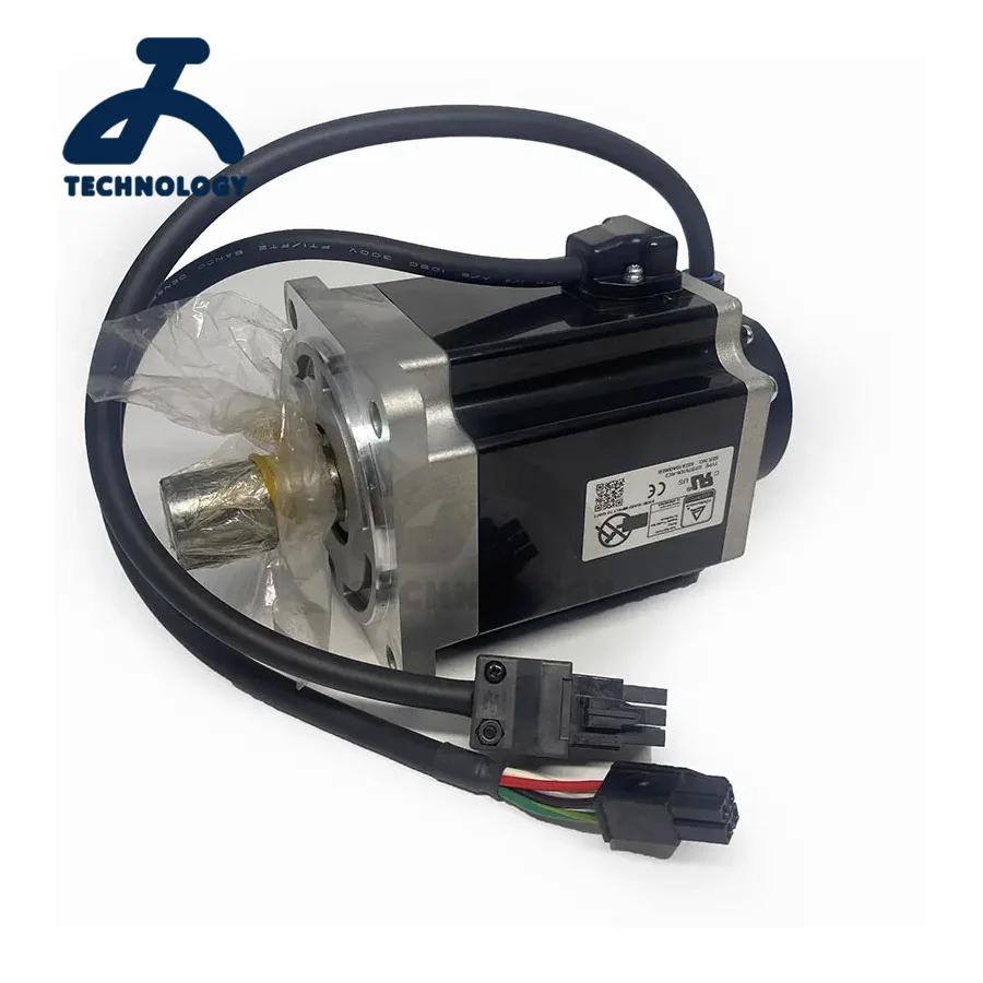
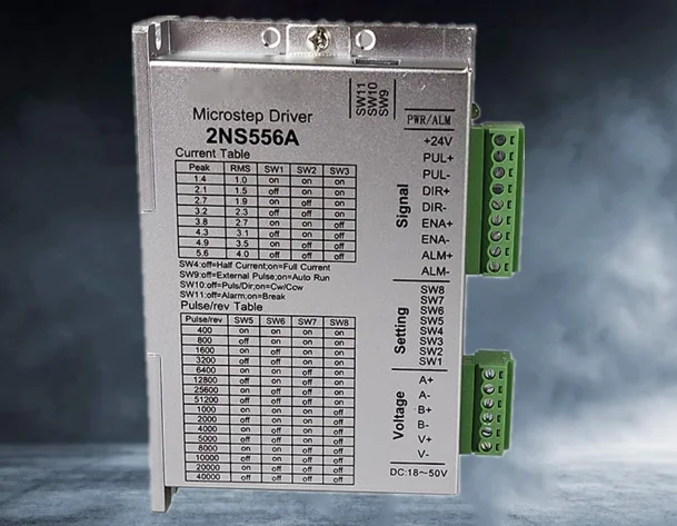
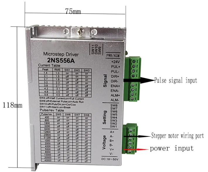
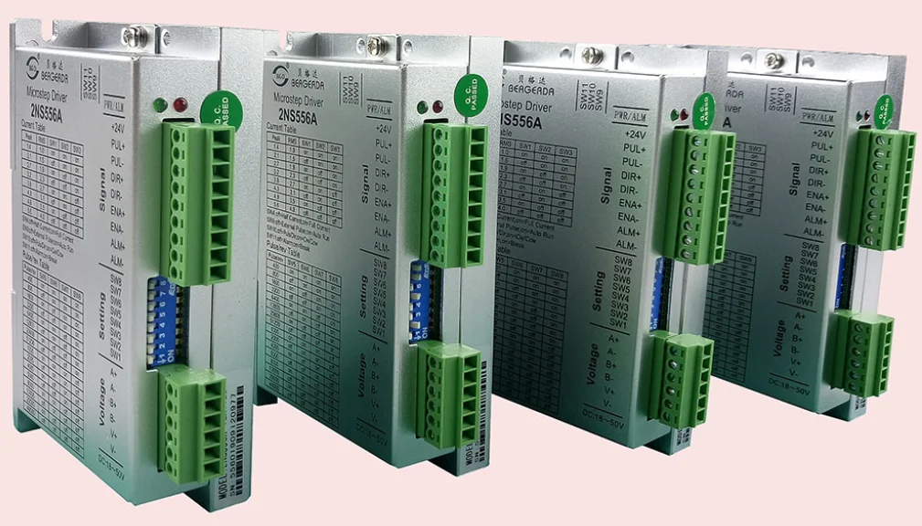
4 x2NS556A drivers
2 x75W24V DC Performance parameter of the DDCS V3.1 1) 16 opto isolated digital inputs,3 opto isolated digital outputs;
2) Upgrade algorithm,support soft interpolation,fixed arc interpolation bug of the old version;
3) Analog spindle control 0-10V spindle control (can be modified as PWM output);
4) 3-4 axis motor Control.Differential Pulse and direction output signal,Max.500Khz per axis;
5) ARM9 main control chip,FPGA core algorithm chip;
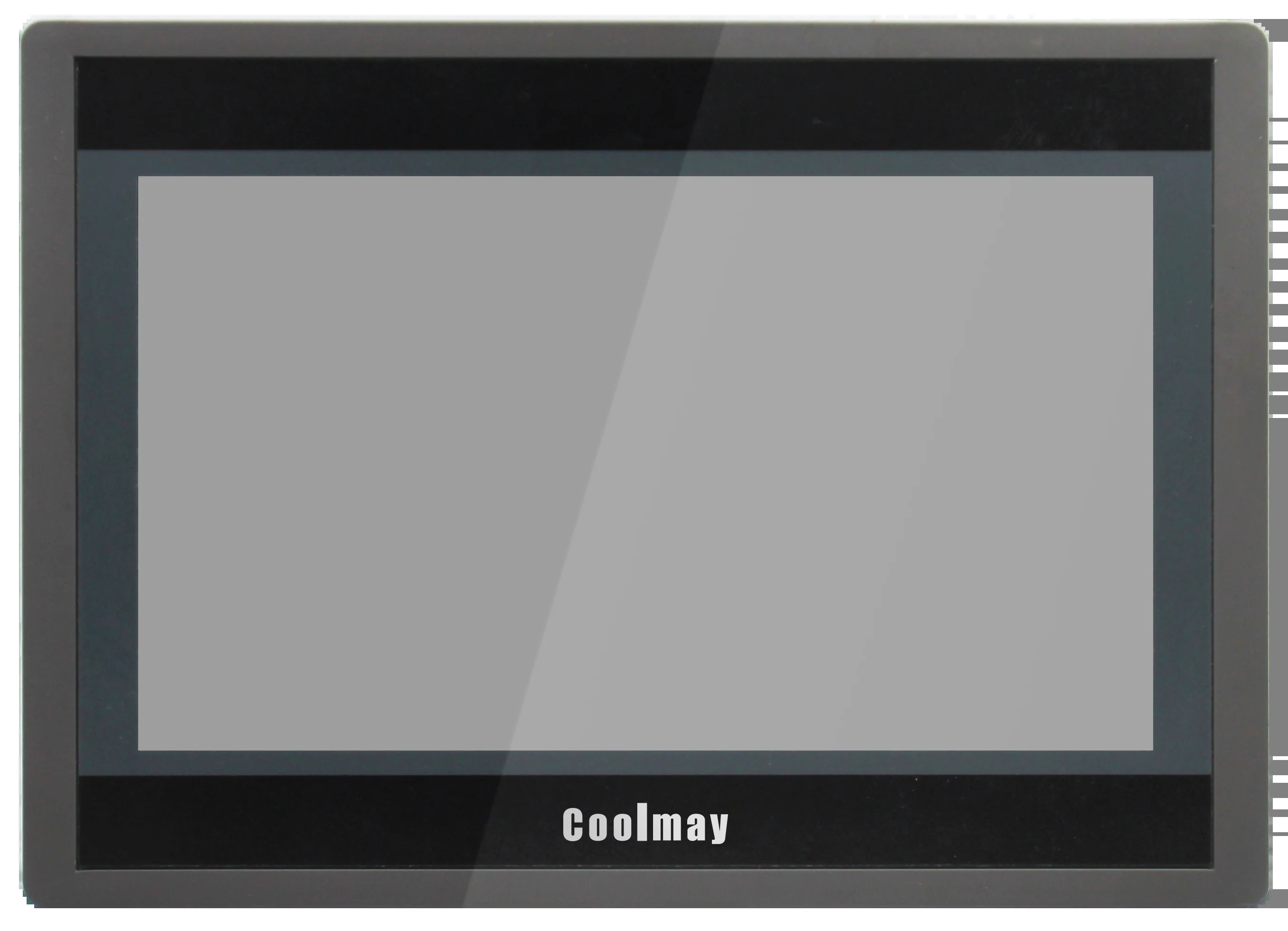
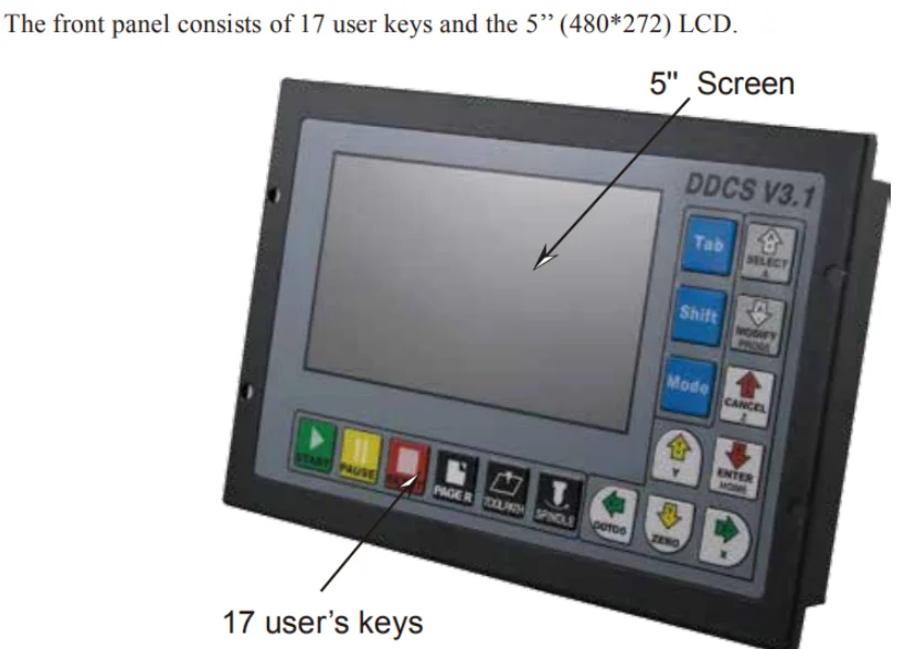
6) 5 inches TFT screen, resolution ratio: 480x272,17 operation keys;
7) 24VDC power input, minimum Current is 0.5A;
8) USB flash disk support for G code file input,no size limited of the G-code file;
9) 1GB internal memory;10) Support standard MPG;
11) Jog function for each axis (continuous, step, defined distance);
12) Support the operation of quickly specify the running position;
13) Support for “Power Cut” recovery. Data is automatically saved;
14) Support the origin and Limit share the same Input ports;
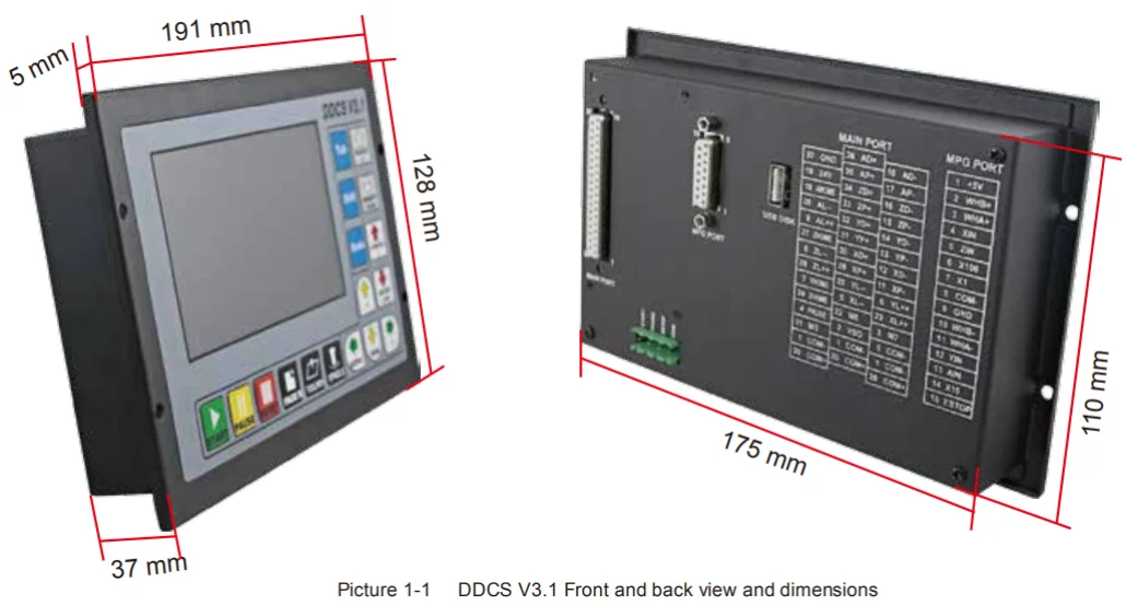
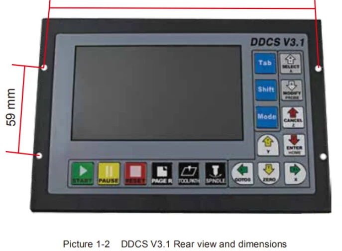
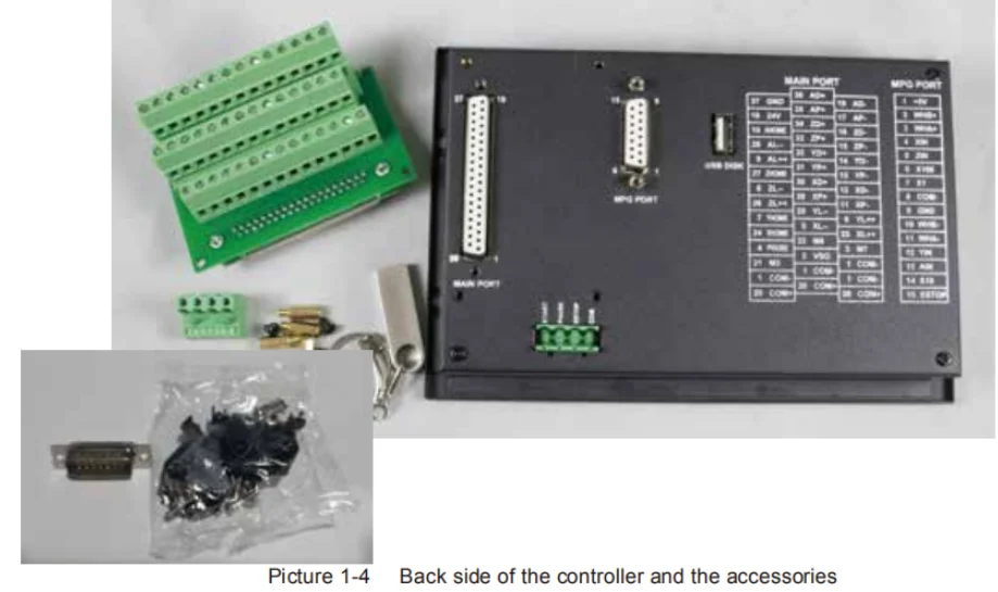
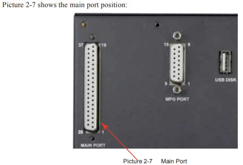
15) The controller only support NPN type limited switch. DDCS V3.1 Appearance and Size At the back side of the controller,there are USB Disk interface,MPG Port,Main Port and external
Start/Pause/Estop interface.
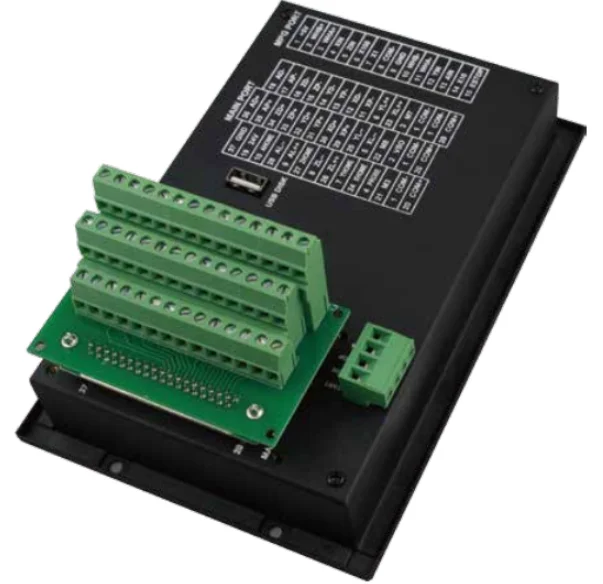
In order to make convenient for the connection,we also apply the 3 layers wiring terminal for main port.
We also supply a DB-15 Ma plug for MPG connection.
The 8 screws are to fix the wiring ternimal and controller.
The U-disk is for the transfer of the G-code file. Explanation of Abbreviations When operating the DDCS, the users will come across some English abbreviations. Here a list with expla�nations.
FRO: Feed Rate Override
SRO: Spindle Rate Override
SRJ: Jog Speed Setting
F: Feed rate, unit is mm/min
S: Spindle Speed, unit rev/min.
X: The coordinate code of the X axis.
Y: The coordinate code of the Y axis.
Z: The coordinate code of the Z axis.
A: The coordinate code of the A axis
BUSY: The system is busy. You still can adjust
FRO and SRO
READY: READY mode, any operation can be done
RESET: Reset mode, controller is in “OFF” mode, no operation can be performed
CONT: Continuous mode, each axis can be manually jogged with the arrow keys
Step :Manual Step Mode,each axis can be jogged in defined steps
MPG: MPG mode. Operate the machine with the MPG (Manual Pulse Generator)
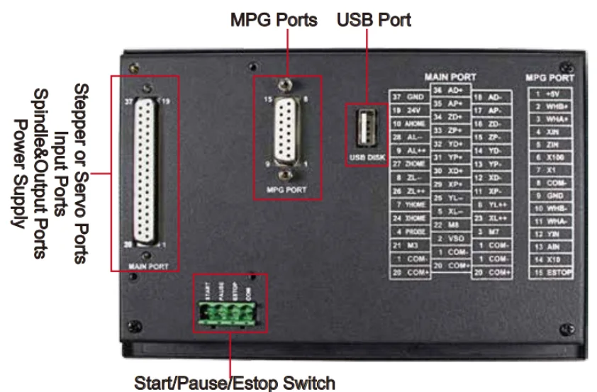
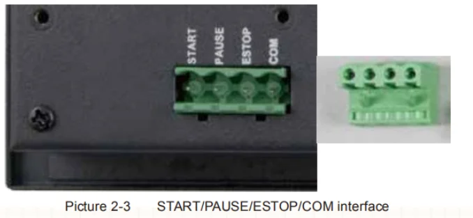
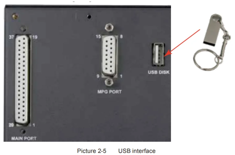
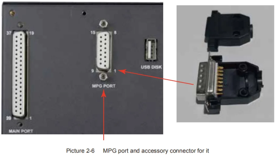
AUTO: Run G code. Auto is showing when file is processing As the picture shows, the wiring section of the controller has Input Ports,Spindle&Output Ports,tepper/Ser�vo control step and direction output,MPG Port, USB Port and Power supply Port. START/PAUSE/ESTOP Switch Wiring As Picture 2-3 shows, the power interface,there is a screw termimal for connection. The marks are the “START”/”PAUSE”/”ESTOP” and “COM” for external switches. And Picture 2-4 is the circuit drawing for the connection. USB Wiring This USB port is the standard USB A-type. A 50cm USB extension cord with installation plug is supplied with the controller. See sketch diagram picture 2-5 for reference. MPG Port The MPG port is shown in Picture 2-6. It is the DB15 Female terminals next to the USB port.
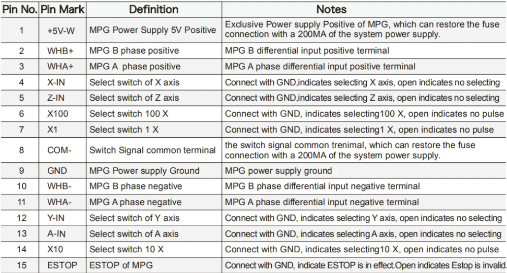
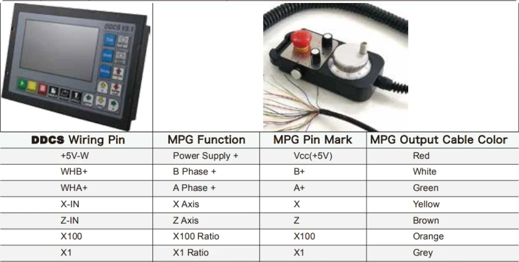
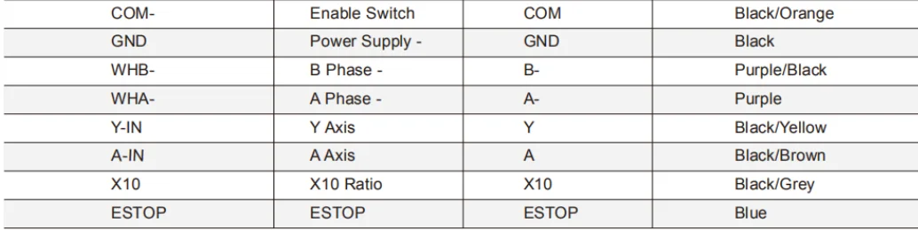
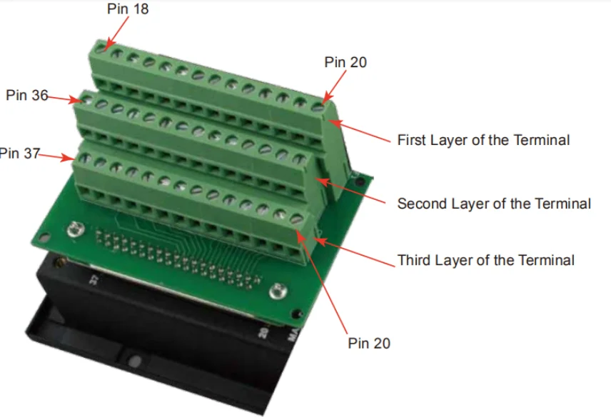
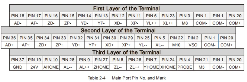
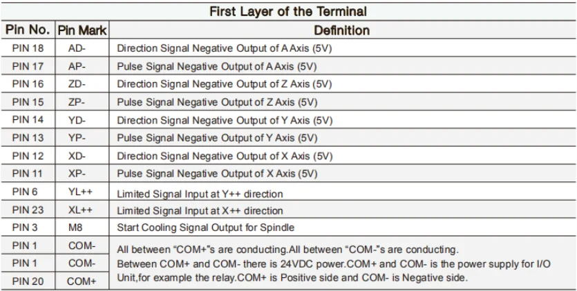
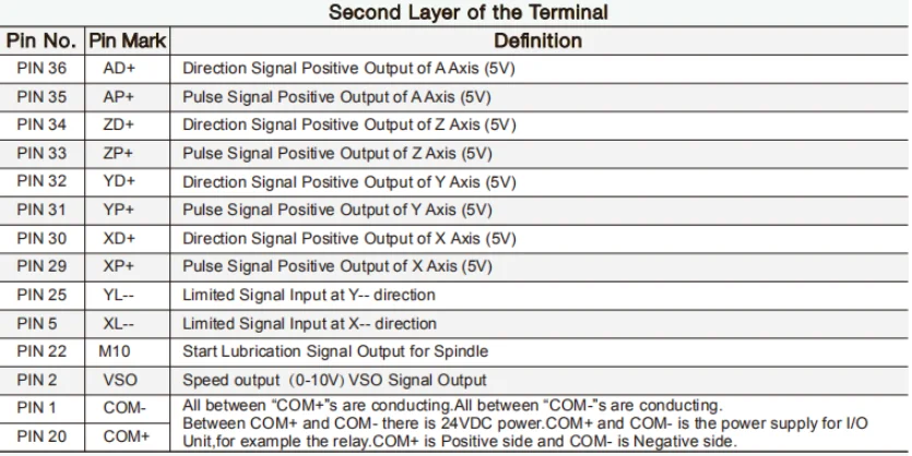
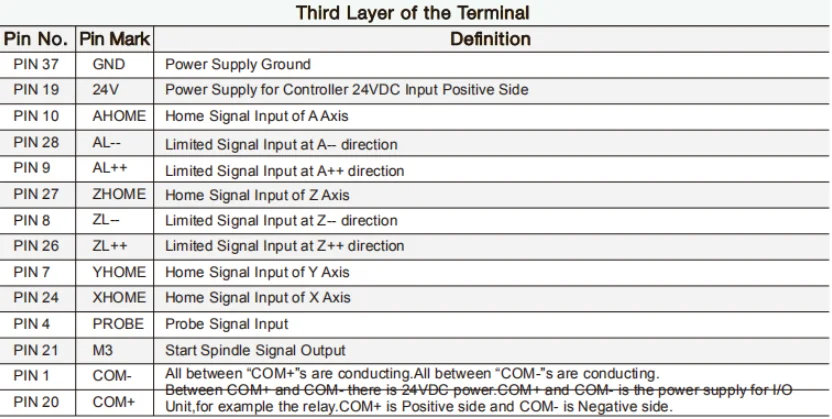
The users need to weld the MPG cables into the DB15 Male terminal,and plug-in to the MPG port of the controller MPG port. The MPG port has 15 pins, see Table 2-1 for reference. See Table 2-2 and table 2-3 for the wiring. We also supply a wiring terminal to fit the 37 female pins,which make the convenient for the wiring.Pls note the following photo.At the termimal 4 conners,there are screws to make the terminal locked-onto the controller There are 3 layers of the Wiring Terminal.Pls note the following photo,which showed the pin No.s and Pin
Mark and definition.It include:
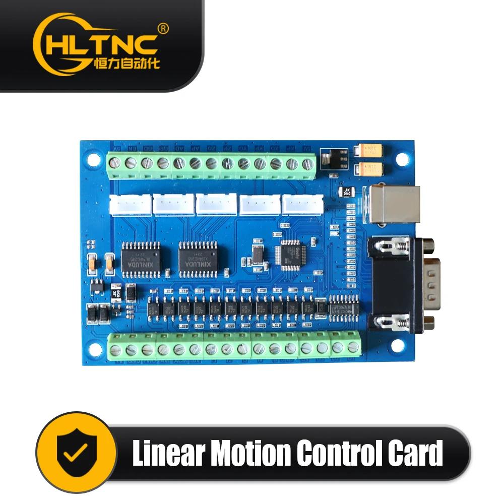
1) Stepper/Servo Output Ports;
2) The Spindle Control Output Ports;
3) The E-stop,Limit,Home and Probe and other Inputs ports;
4) 24V DC Power Supply ports for the Controller;
5) 24V DC Power Supply ports for the I/O Unit.
|
|
|
|
|


 배송기간
배송기간