|
|
     aHR0cDovL2ZyZWVzaGlwLmNvLmty aHR0cDovL2ZyZWVzaGlwLmNvLmty
- 신청: 밀링 머신
- 모델 번호: ddcsv2.1
- 근원: CN (정품)
packing list:
1 xCNC controller DDCSV2.1 has 3/4 axis optional
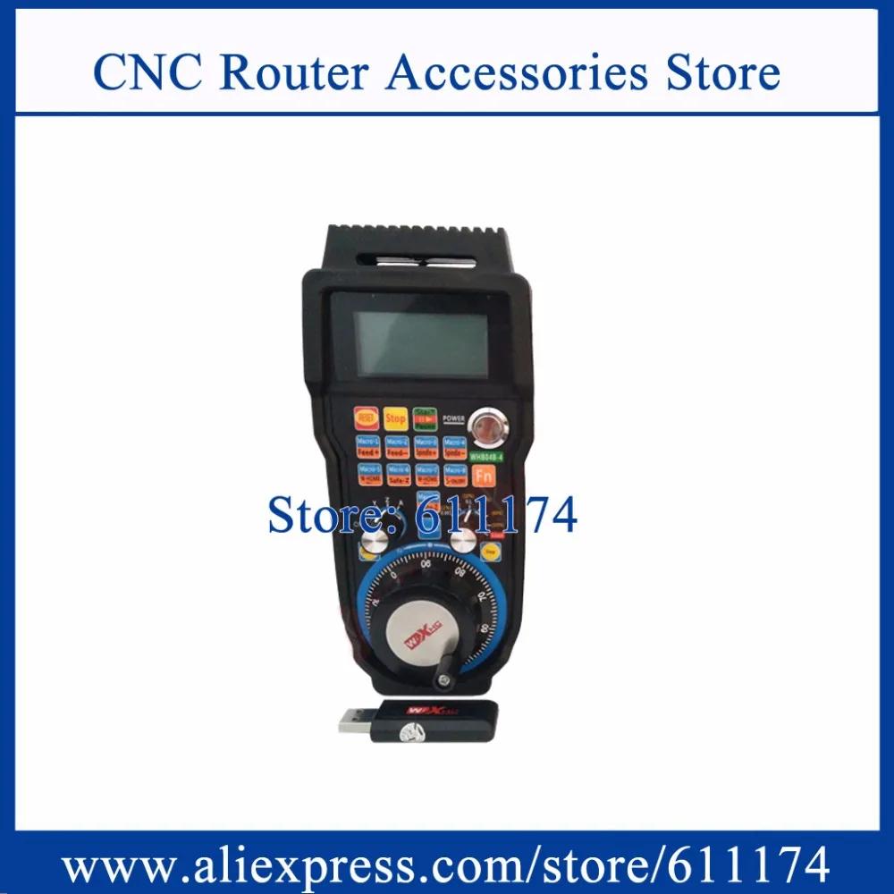
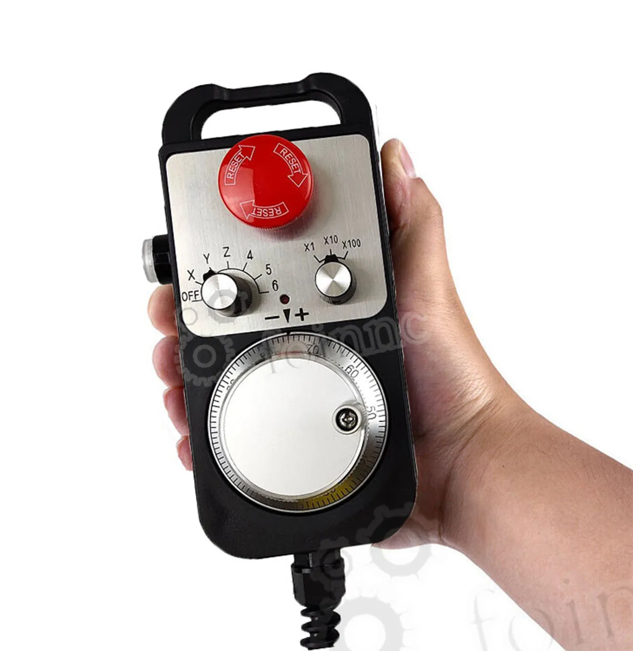
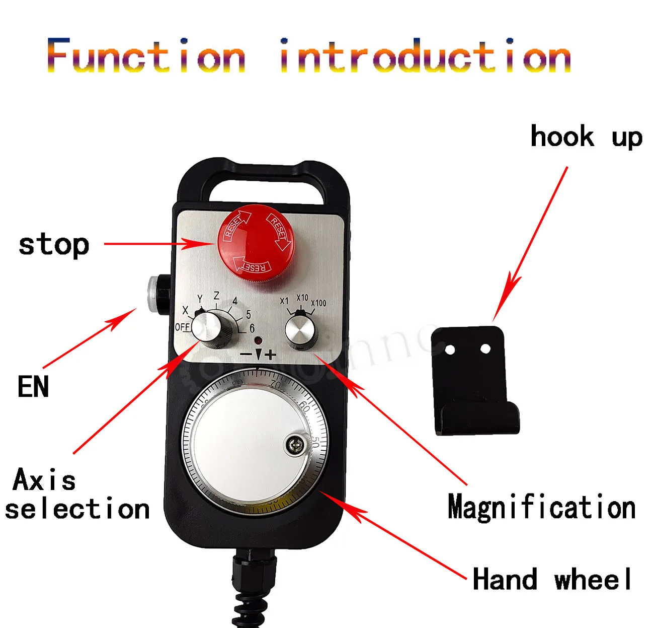
1 x handwheel
2 x fixed terminal VDC
1 x U Disk
1 x U disk extension cable  Product introduction:
The DDCSV2.1 is the 4 axis and 4 axes motion controller which has been researched
and developed by Faster CNC for four years. The control period of each position is only 4
milliseconds, with a high control precision. The highest uniaxial output pulse is 500KHz and
the pulse width can be adjusted. It supports the common stepper motor and servo motor.
The DDCSV2.1 numerical control system adopts the ARM+FPGA design framework.
The ARM can finish the part of human-computer interface and code analysis and the FPGA can
finish the part of underlying algorithm and control pulse generate, with the reasonable design,
reliable control and easy operation.
The panel layout structure of DDCSV2.1 is rational. The common off-line operation
can be finished only by 17 keys and it supports the FANUC with high universality to be
compatible with G code set.
Product performance parameters:
Ordinary digital input interface of 16-circuitoptocoupler coupling isolation
? Ordinary digital input interface of 3-circuit optocoupler coupling isolation
? Output interface of 0-10V spindle control port with analog quantity(can be
modified as PWM output);
? Support the 4 axis stepper motor control, the highest control pulse output of
single axis is 500KHz;
? ARM9 main control chip;
? FPGA core algorithm chip;
? 4.3 inches TFT screen, resolution ratio:480*272;
? 17 operational keys;
? The main control equipment is 18V-32V power input, the current capacity is
required not to be lower than 0.5A;
? Support the USB flash disk to read the G code,and the size of G codefile has no
requirement;
? Be equipped with MPG port and support digital display MPG as well as support
the general MPG in the market.
? Support the panel key with single-axis manual operation, manual step and
CONToperation;
? Support the operation of quickly specify the running position;
? Support the multi coordinate systems (with automatically saving function in case
of power cut);
? Support the function of saving data automatically after power down (press the
start to automatically save the data in the operation, automatically save the data
Product appearance structure and size:
The DDCSV2.1 adopts the embedded shell structure, which can punch a square
hole on the equipment cabinet and then embed this equipment in the squire hole.
Use two locking mechanism from the inside can fix this equipment on the
equipment cabinet, with easy installation. The dimension figure of the product’s
outward appearance are as picture 1-1 and picture 1-2.
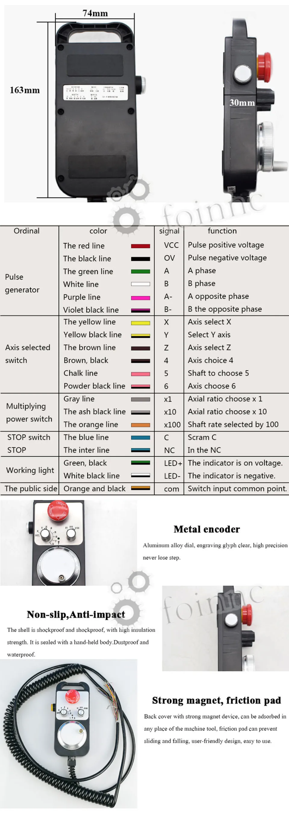
The panel size of the product is 163mm*102mm*5mm;
The size of main body is 156mm*93mm*45mm;
The size of square hole installed on the equipment cabinet is 156mm*93mm。
The front of the product is 17 user keys and 1 4.3’’and 480*272 LSD (Liquid Crystal
Display), and the reverse side is input signal, spindle control, stepper/ servo control, MPG and
other four sets of interfaces as well as USB interface and power interface. Please look at the
reference picture Explanation of Nouns:
When operating the DDCSV2.1, the users will come across some English abbreviation.
Now all the abbreviations are listed to users for references.
FRO: the FRO mainly refers to adjust the FRO value to amend the current feed rate
under the situation that the F value has been confirmed before the processing course or in the
processing course. The actual rate F#=setting rate F*FRO.
SRO: the SROrate mainly refers to adjust the SROrate to amend the current speed of
spindle under the situation that the S value has been confirmed before the processing course or
in the processing course. The actual speed of spindleS#=setting rate S* SRO.
SRJ: SRJ, under the situation that the defaultvalue ofmanual operation rate has been
set, it is impossible to set the value again to amend the manual operation rate when it is
required to adjust the manual operation speed and CONToperation speed. At this moment, the
SRJ value can be modified to realize the purpose of amending the manual operation speed. The
actual speed of manual operation FS#=setting manual operation speed SRJ*.
F: Feed rate, the unit is mm/min. For example F=2000, indicates that it can feed
2000mm per minute;
S: speed of spindle, the unit is rad/min. For example S=20000, indicates that it can
rotate 20000 per minute;
X: The coordinate code of X axis.
Y: The coordinate code of Y axis.
Z: The coordinate code of Z axis.
A: The coordinate code of A axis
Busy: Server busy, it cannot conduct the processing operation, and parts of the
function are open. For example, amend the FRO and value of SRO.
REDAY: REDAY mode, any operation can be done at this time, including the
processing or modifying the parameter or starting the 2nd mode
Reset: reset mode, all the operations are forbidden to do at this time.
“CONT”: continuous operation, each axis can conduct the CONT operation under this
mode.
“Step”:Manual step mode,each axis can conduct the manual step operation under
this mode
MPG: MPGMode, each axis can conduct the MPG operation under this mode
AUTO: Automatic processing mode, it will show AUTO when enters the state of
automatic processing.
Equipment power scheme:
In general, the power supply solution of industrial control’s equipment products is
complex. It has many different ground levels. Now the internal power supply structure of this
product is described as follows:
The power supply structure of this product is as the picture 2-1. The Master Power
Supply input and MPG module and stepper control module have the same ground. Limits
ESTOP and other input modules as well the spindle speed control output /M3/M8/M10 and other
output modules have the same ground, which are used the electric isolation among them. The
limits ESTOP and other input modules are connected with the same positive. The internal of the
equipment provides a 12V as the common + port, without the requirement of the external power
source. As for the spindle rate port, take the output ground for references and output a 0-10V
adjustable voltage as the use of spindle speed adjust. The M3/M8/M10 digital output port is the
open drain signal. If it is required to externally connect a relay, it is necessary to take the output
ground for reference, thus providing the external power supply for the relay.  Equipment power scheme:
In general, the power supply solution of industrial control’s equipment products is
complex. It has many different ground levels. Now the internal power supply structure of this
product is described as follows:
The power supply structure of this product is as the picture 2-1. The Master Power
Supply input and MPG module and stepper control module have the same ground. Limits
ESTOP and other input modules as well the spindle speed control output /M3/M8/M10 and other
output modules have the same ground, which are used the electric isolation among them. The
limits ESTOP and other input modules are connected with the same positive. The internal of the
equipment provides a 12V as the common + port, without the requirement of the external power
source. As for the spindle rate port, take the output ground for references and output a 0-10V
adjustable voltage as the use of spindle speed adjust. The M3/M8/M10 digital output port is the
open drain signal. If it is required to externally connect a relay, it is necessary to take the output
ground for reference, thus providing the external power supply for the relay. Master page:
The software interface totally contains 3 pages, including main page, file page and
configuration page. Now the 3 pages are described as follows
|
|
|
|
|


 배송기간
배송기간