|
|
     aHR0cDovL2ZyZWVzaGlwLmNvLmty aHR0cDovL2ZyZWVzaGlwLmNvLmty
- 브랜드 이름: NEJE
- 증명서: 세륨,FCC,ROHS,Ul
- 근원: CN (정품)
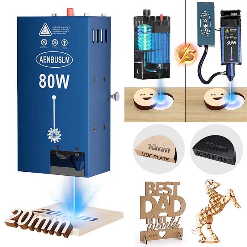
- 모델 번호: A40640/N40630
옵션정보[(350853)N40630 Driver Board] [(10)A40640 Driver Board] [(10)A40640 Driver Board] Packing List: Driver Board(Main driver board + Switch Board) x 1 12V soldering iron x 1 500mm solder x 1 Flux x 1  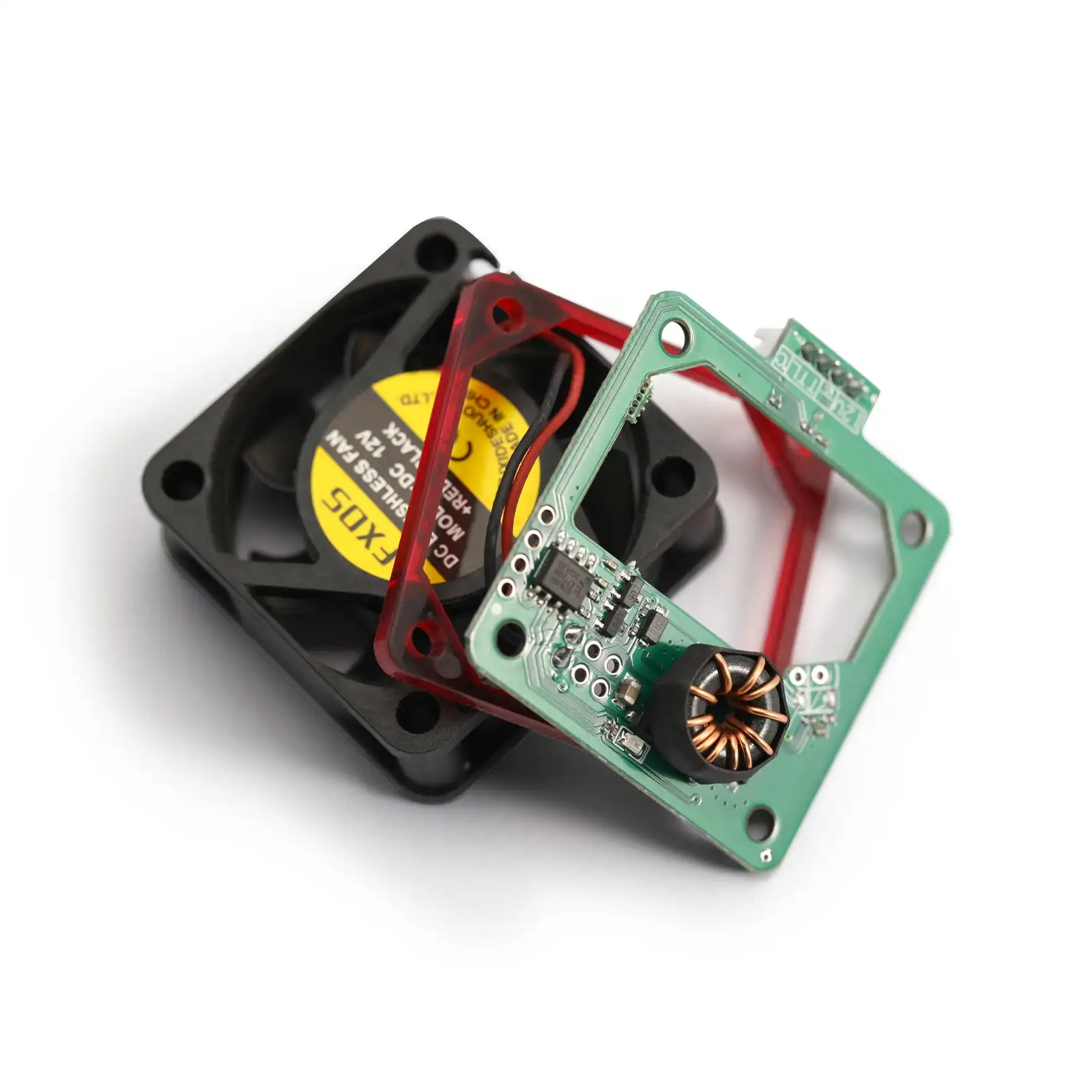 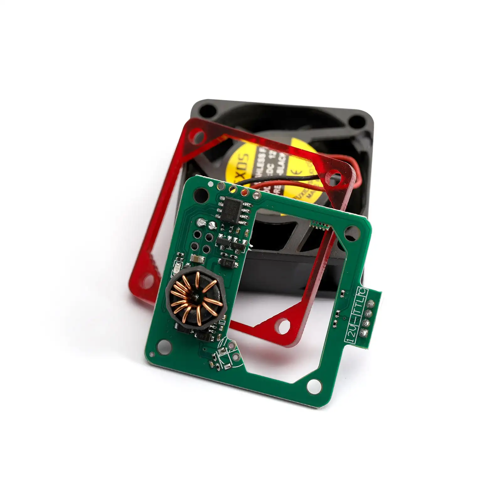 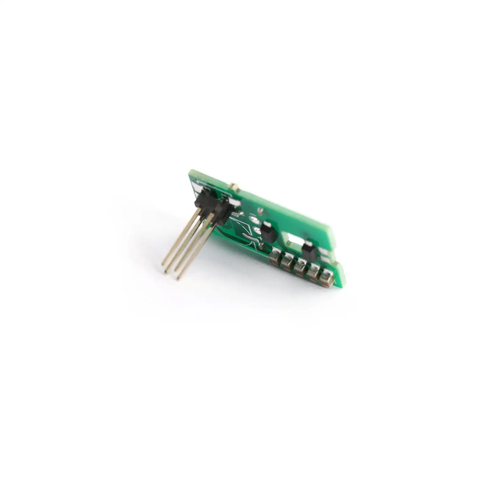 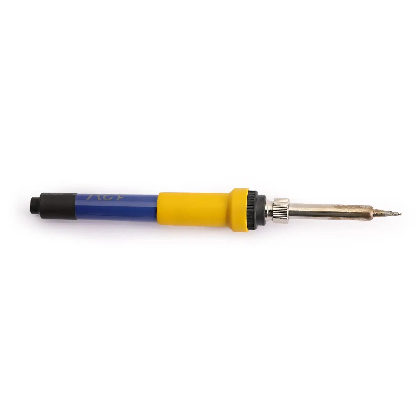 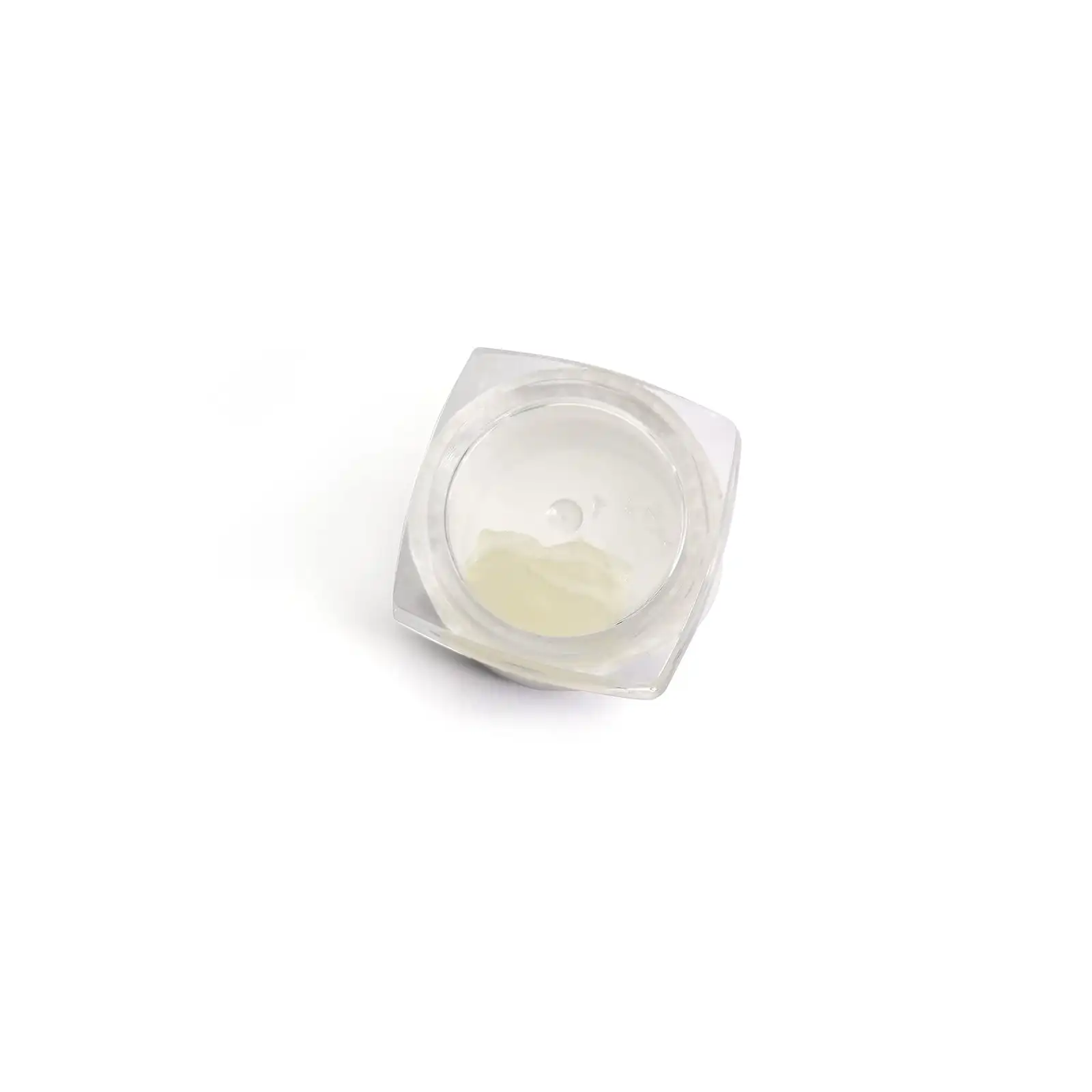 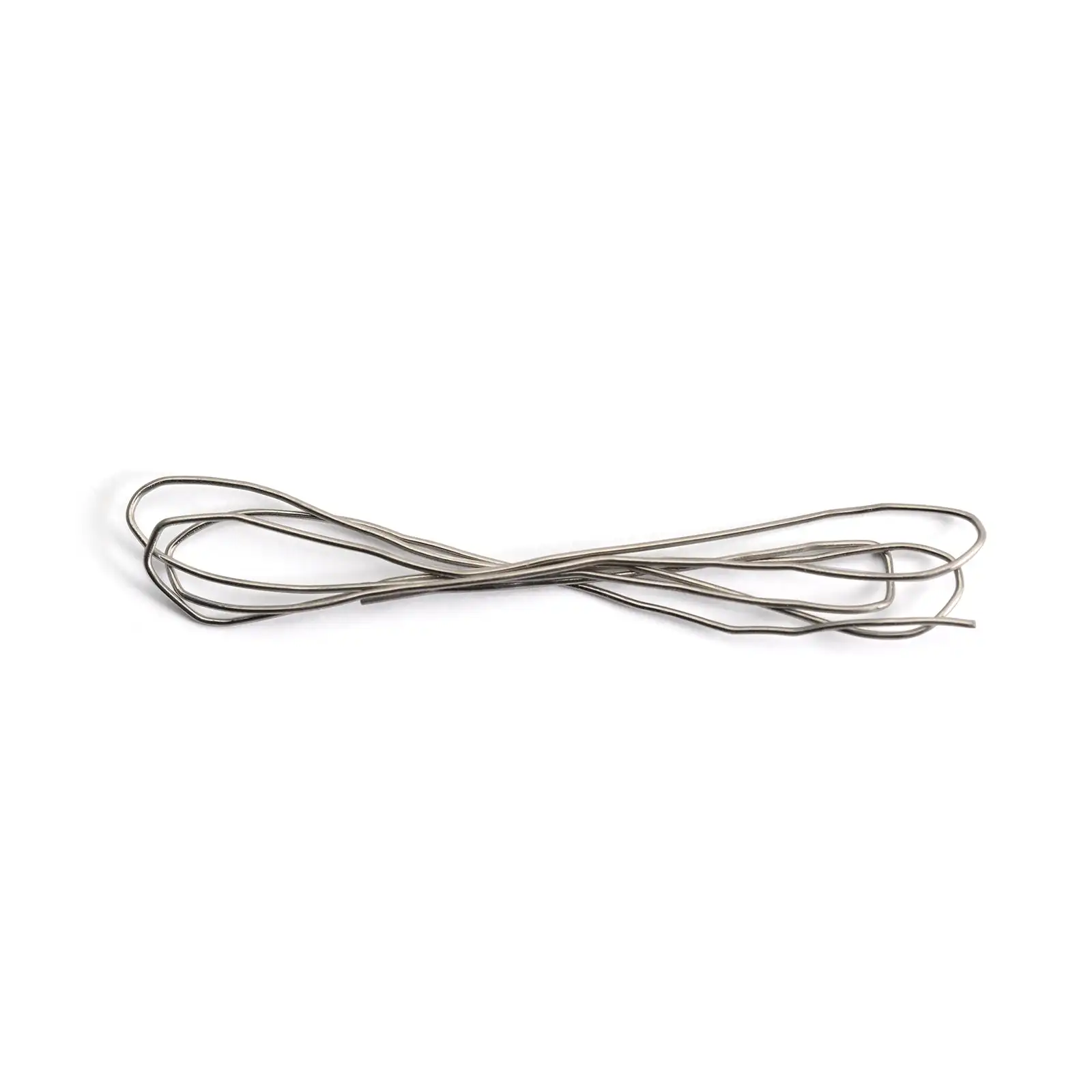
NOTE:
When operating the soldering iron, please pay attention to the high temperature and don’t hurt yourself High temperature of the soldering iron may damage the control board. Please ensure that the soldering iron does not heat the control board for more than 3 seconds
How to change control board for laser module?
First, disassemble your laser drive and heat up your iron(may take 3 minutes) Add enough solder to make all 4 pins have solder, as shown in the figure below: Heat the four pointsat the same time, and gently lift the control board with your left hand. If the method is correct, you can quickly separate the drive board and the main body(If you find it difficult to remove, try applying some flux to the soldering area) When you successfully remove the driver board, a lot of solder may remain on the pins. You need to clean them. How to clean the pins? Step 1: Apply the flux to pins (Click on image to enlarge image) Apply on pins that need to clean Step 2: Tilt your laser module down, touch the soldering iron to the pins(make sure your iron is clean, clean it with napkin) Tilt your module upside down Touch the soldering iron to the pins This is the expected effect Put on new control board: Welding new drives: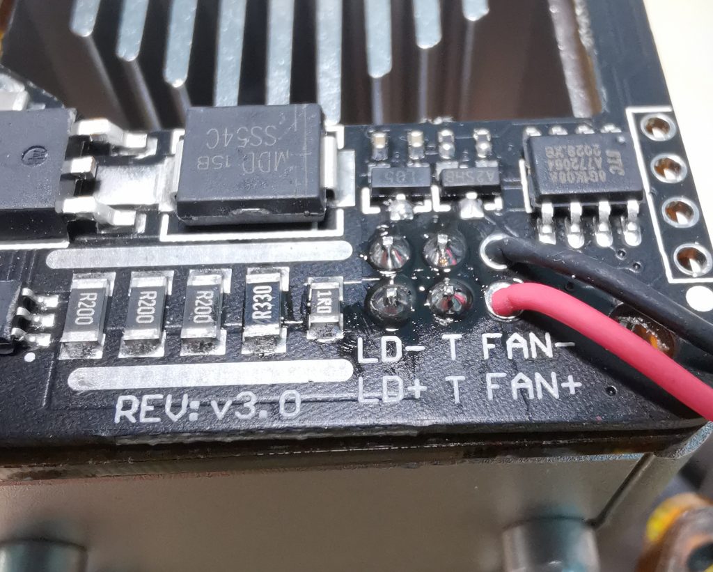
|
|
|
|
|


 배송기간
배송기간