|
|
     aHR0cDovL2ZyZWVzaGlwLmNvLmty aHR0cDovL2ZyZWVzaGlwLmNvLmty
- 모델 번호: DF-96D DF-96DK DF-96A
- DIY 용품: ELECTRICAL
- 브랜드 이름: DMWD
- 원산지: 중국
옵션정보[(366)DF-96A] [(200003699)DF-96D No switch] [(200003699)DF-96D No switch] [(200002984)DF-96DK with switch] [(200002984)DF-96DK with switch] [(201800840)3 wires (no DF-96D)] [(201800840)3 wires (no DF-96D)]
| Option |
Package include: |
Content |
| Option1 |
DF-96A |
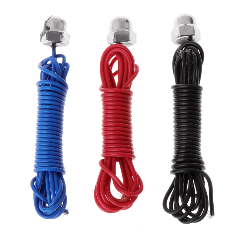
1 X DF-96A/B and 3x 2m Proble wires |
| Option2 |
DF-96ED without switch |
DF-96ED without switch and 3x 2m Proble wires |
| Option3 |
DF-96ED with switch |
DF-96ED with switch and 3x 2m Proble wires |
| Option4 |
3x 2m Proble wires |
Only 3 x 2m Proble wires |
Single-control UP pool (water storage) installation instructions shown in figure 1
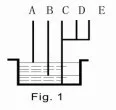
A(red)?Upper water level control point. When water level gets to A point,
the probe touch water and controller can stop the pump by auto.
B(blue)?Lower water level control point. When water level gets off B point,
the probe out of reach water and controller can start the pump by auto.
C(black)?Should be placed in bottom of pool as the common line.
D(green) and E(yellow)are connected with C (black).
Single-control DOWN pool(drain water)installation instructions shown in figure 2.

E?Upper water level control point. When water level gets to E point,
the probe touch water and controller can start the pump by auto.
D?Lower water level control point. As liquid level gets off D point,
the probe out of reach water and controller can stop the pump by auto.
C?Should be placed in bottom of pool as the common line.
A&B?disconnected
1 . Lack of water protection installation instructions shown in figure 3.

C&D?Lower water level control points. When water level gets off this point,
C or D probe out of reach water and controller can stop the pump by auto.
E&C?short-connected;
A&B?disconnected
2 . Joint control UP and DOWN pool installation instructions shown in figure 4.

A?Upper water level control point in UP pool. When water level gets to A point,the probe touch water and controller can stop the pump by auto.
B?Lower water level control point in UP pool. When water level gets off A point, the probe out of reach water and controller can start the pump by auto.
C?Should be placed in bottom of UP and DOWN pools as the common line.
D?Lower water level control point in DOWN pool. When water level gets off D point, the probe out of reach and controller can stop the pump by auto.
E?Upper water level control point in DOWN pool. When water level gets to E point, the probe reach water and controller can start the pump by auto. Then pool starts to drain water. If not, E point disconnected
Used to solve problem:
1. On power but no work:
a. Check the red indicator is on or not. If not, make the connection is good enough;
2. When water level is above or below probes but the pump does not start or stop by auto, Please check it like the following.
a. Whether the probe is placed too high or low so that water level can reach or out of reach it;
b. The connection of upper &lower line or probe is dislocation by error or short connected;
c. To check the probe whether it is rust or not or the connection is good enough.
d. C- Check the common line whether it is placed in the lowermost bottom of pool.

|
|
|
|
|


 배송기간
배송기간