|
Packaging Details - Unit Type: piece
- Package Weight: 0.3kg (0.66lb.)
- Package Size: 15cm x 15cm x 10cm (5.91in x 5.91in x 3.94in)
Packaging Details - Unit Type: piece
- Package Weight: 0.3kg (0.66lb.)
- Package Size: 15cm x 15cm x 10cm (5.91in x 5.91in x 3.94in)
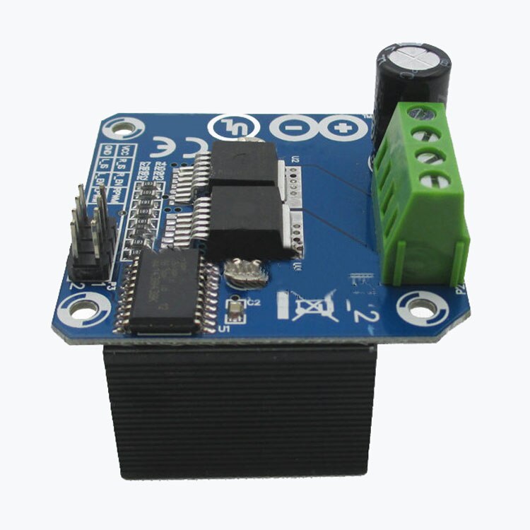
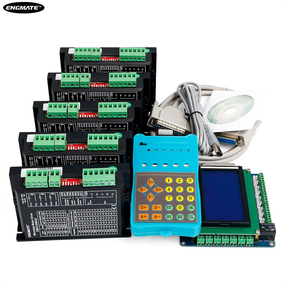
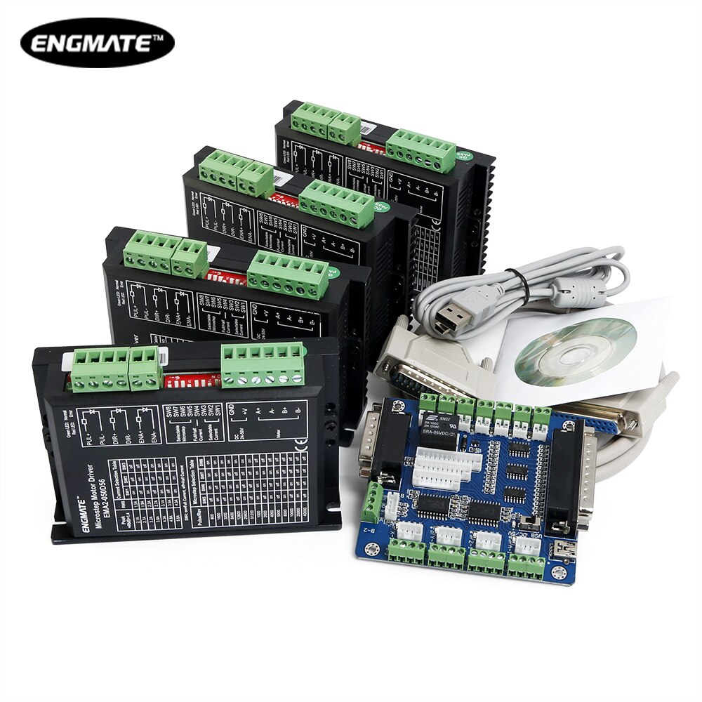
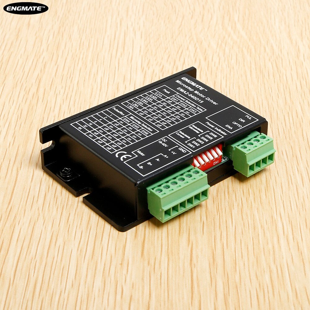
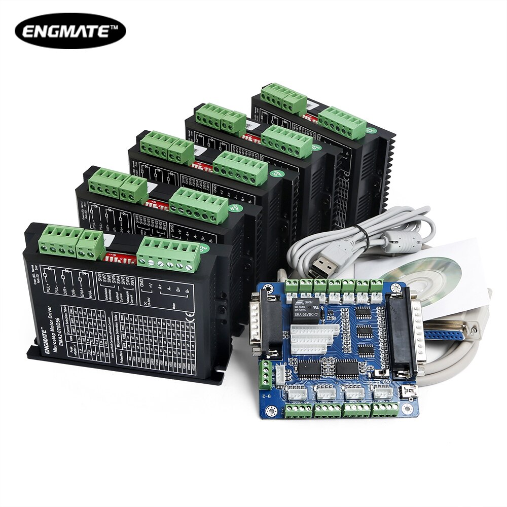
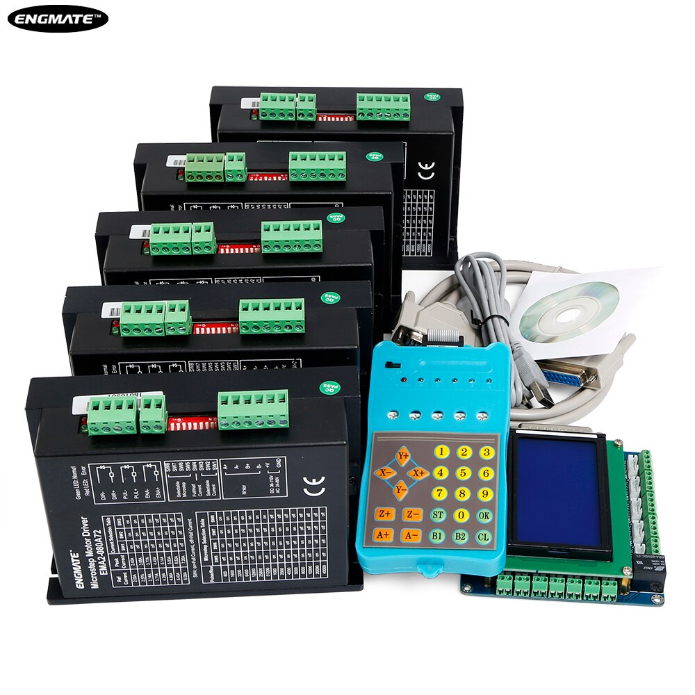
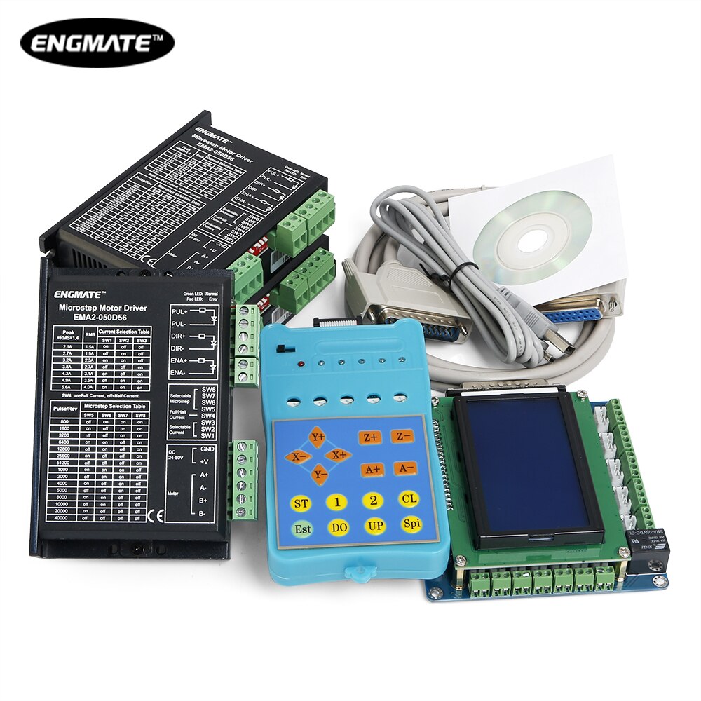
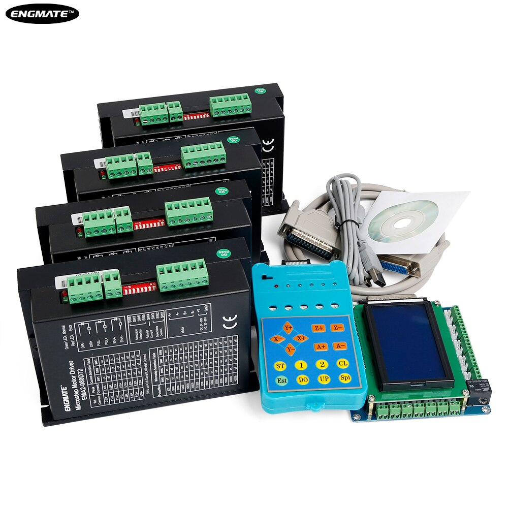
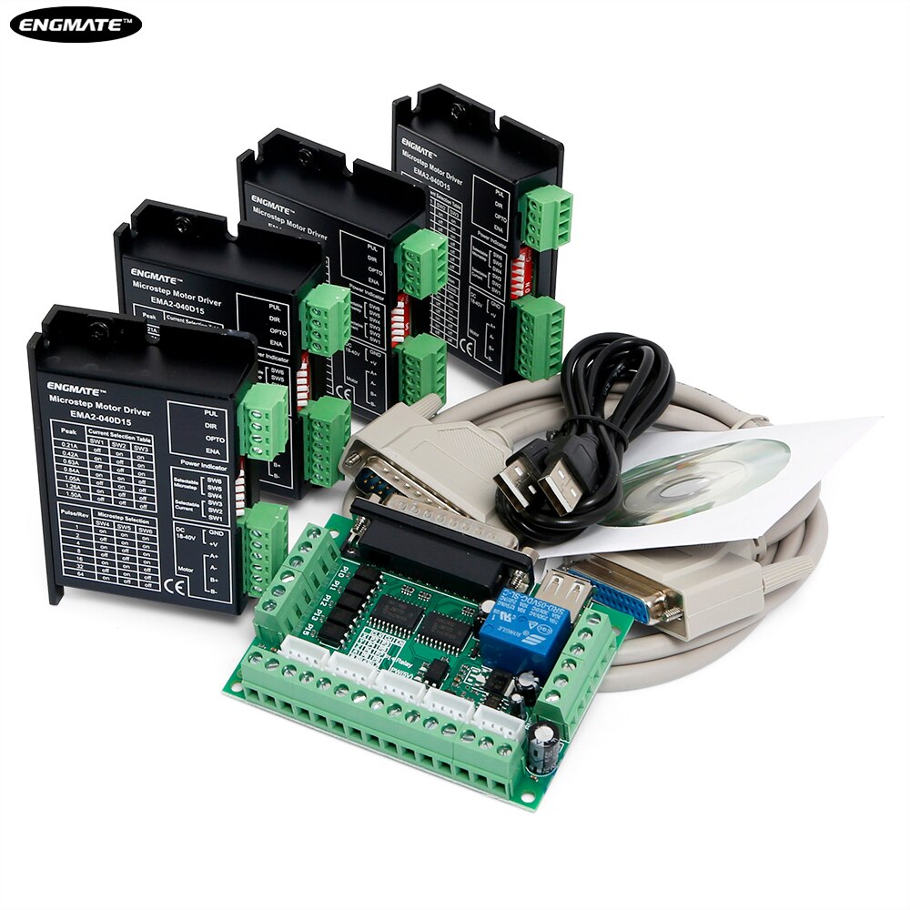
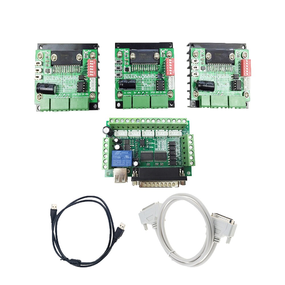
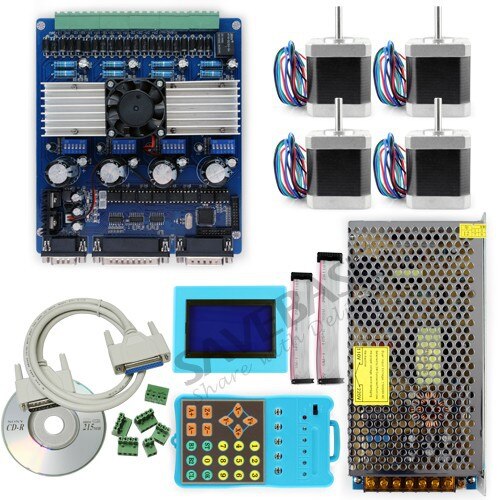
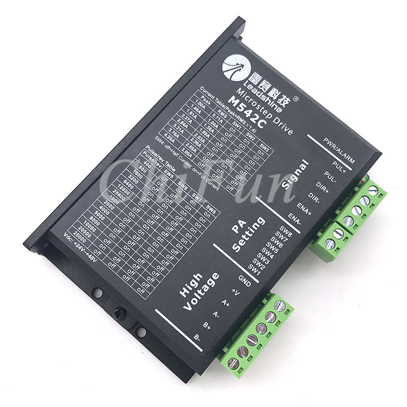
t; This driver is an upgraded version of TB6600, subdivision increased to 32 subdivision, suitable for high-subdivision purposes. For stepper motor: 42, 57, 86 \`type 2 phase 4 phase (4 lines 6 lines 8 lines) 1,9V-42V DC power supply; 2, H bridge bipolar constant current drive; 3, the maximum output current of 4.0A eight optional; 4, the maximum 32 subdivision of the 6 subdivision modes optional; 5, high-speed optical input signal isolation; 6, the standard common positive single pulse interface; 7, keep functions offline; 8, semi-enclosed chassis can adapt to more harsh environment; 9, to provide energy-saving semi-automatic current lock function; 10, built-in temperature protection and over-current protection. Terminal definition description: Signal input ⑴ CP +: positive pulse signal input. ⑵CP-: pulse signal input negative terminal. ⑶DIR +: positive and negative motor control positive end. ⑷ DIR-: motor is positive, negative control negative end. ⑸ EN +: motor offline control is positive. ⑹EN-: Motor offline control negative terminal. Motor winding connection: ⑴ A +: Connect motor winding A + phase. ⑵ A-: Connect the motor winding A-phase. ⑶B +: connect the motor winding B + phase. ⑷ B-: connecting the motor winding B-phase. Operating voltage connection: ⑴VCC: DC power supply positive (Note: 10V ⑵GND: negative DC power supply. Signal input optocoupler isolation connection: Input signal interface has two kinds of connection: the user can use common anode connection or common cathode connection. 1. Common anode connection: connect CP +, DIR + and EN + to the control system respectively. If the power supply is + 5V, it can be connected directly. If the power supply is greater than + 5V, an additional current limiting resistor R , To ensure that the internal optical drive to provide drive 8-15mA drive current. Pulse input signal through the CP-access; At this time, DIR-, EN- in the low-effective. 2. Common Cathode Connection: Connect CP-, DIR- and EN- to the ground of control system (SGND, isolated from power supply) respectively; + 5V pulse input signal is added through CP +; at this moment, DIR +, EN + High effective. The current-limiting resistor R is connected in the same way as the common-anode connection. Note: EN terminal can not be connected, EN is valid when the motor rotor is free (offline), then you can manually rotate the motor shaft, do the adjustment for you. After the manual adjustment is completed, set EN to inactive to continue the automatic control. Microstpper settings: | Micro STP | Pulse/rev | S1 | S2 | S3 | | NC | NC | ON | ON | ON | | 1 | Two hundred | ON | ON | OFF | | 2/A | Four hundred | ON | OFF | ON | | 2/B | Four hundred | OFF | ON | ON | | 4 | Eight hundred | ON | OFF | OFF | | 8 | One thousand and six hundred | OFF | ON | OFF | | Sixteen | Three thousand and two hundred | OFF | OFF | ON | | 32 | Six thousand and four hundred | OFF | OFF | OFF |
Current setting: | Current (A) | PK Current | S4 | S5 | S6 | | Zero point five | Zero point seven | ON | ON | ON | | One | One point two | ON | OFF | ON | | One point five | One point seven | ON | ON | OFF | | Two | Two point two | ON | OFF | OFF | | 2.5 | Two point seven | OFF | ON | ON | | Two point eight | Two point nine | OFF | OFF | ON | | Three | 3.2 | OFF | ON | OFF | | Three point five | 4.0 | OFF | OFF | OFF |
 -->
|


 배송기간
배송기간