Product Package
1 x DM500 Control Board 1 x DM500 Control Panel 1 x USB Flash Disk
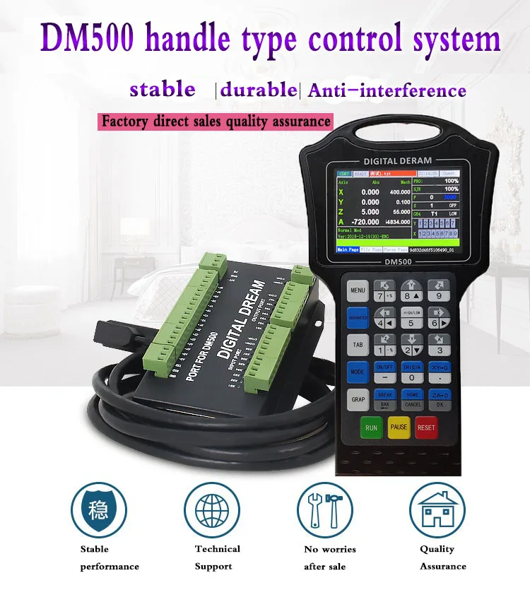
Product Description
DM500 is very professional 3/4 Axis CNC Motion Controller which is based on embedded system.DM500 operates as a standalone system without the need of a computer,and with a pendant,it makes users very conve�nient to opreate the machines.Our controller adopts Embedded Operating System,by which the controller will never get virus-infected.And the controller adopts look-ahead algorithm by which the the controller can read more ahead 30-lines G-code than the operating.All the features guarantees high precision,accuracy and reliabili�ty.And the size is very small,oepreation is very easy,very suitable for all size of Engraving machines,Milling machines and cutting machines and so on.
Performance parameter of the DM500
1) Max. 4 Axis;2-4 Axis linear interpolation,any 2 axis circular interpolation;
2) 7 opto isolated digital outputs,8 opto isolated digital inputs;
3) Support every Input and output port definition by users.
4) The controller need 2 power supply,one power supply is for system power,one is for input and output
ports power.Both input power is 24V,2A.
5) Open-collector output, Max. output current is 500mA,can power the relay directly;
6) Differential Pulse and direction output signal,Max. 500Khz per axis;
7) Spindle Control: 3 I/O ports control 8 different speeds(3 lines 8 speeds),1 I/O control the Start/Stop;
8) The System Support standard G-code.Also Support the popular CAD/CAM software,such as ArtCam,-
MasterCam,ProE and so on.
9) USB flash disk support for G code file input;
10) The control system can preview the process path before machining,and it makes the system more
steady,working smoothy and precise;
11) Acceleration/Deceleration Mode: S curve;
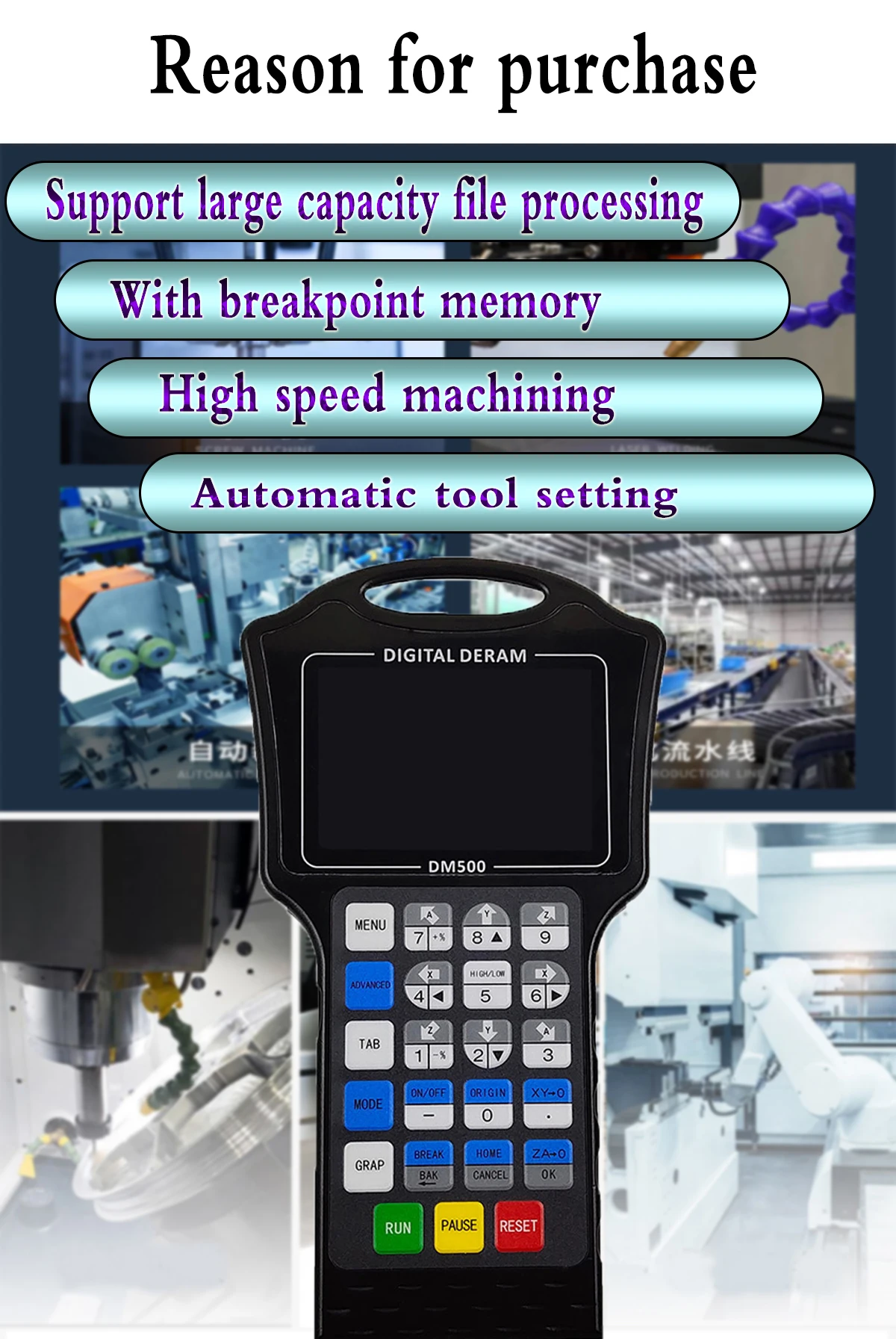
12) Support un-limited size file for machining;
13) Manual/Automatic machining function;
14) Support the operation to Start a G code from a specific line;
15) Support for “Power Cut” recovery. Data is automatically saved;
16) Support time-lock function;
17) Support 4 kinds operation rights:visitor,operator,admin,super admin;
Appearance, Structure and Size of Product
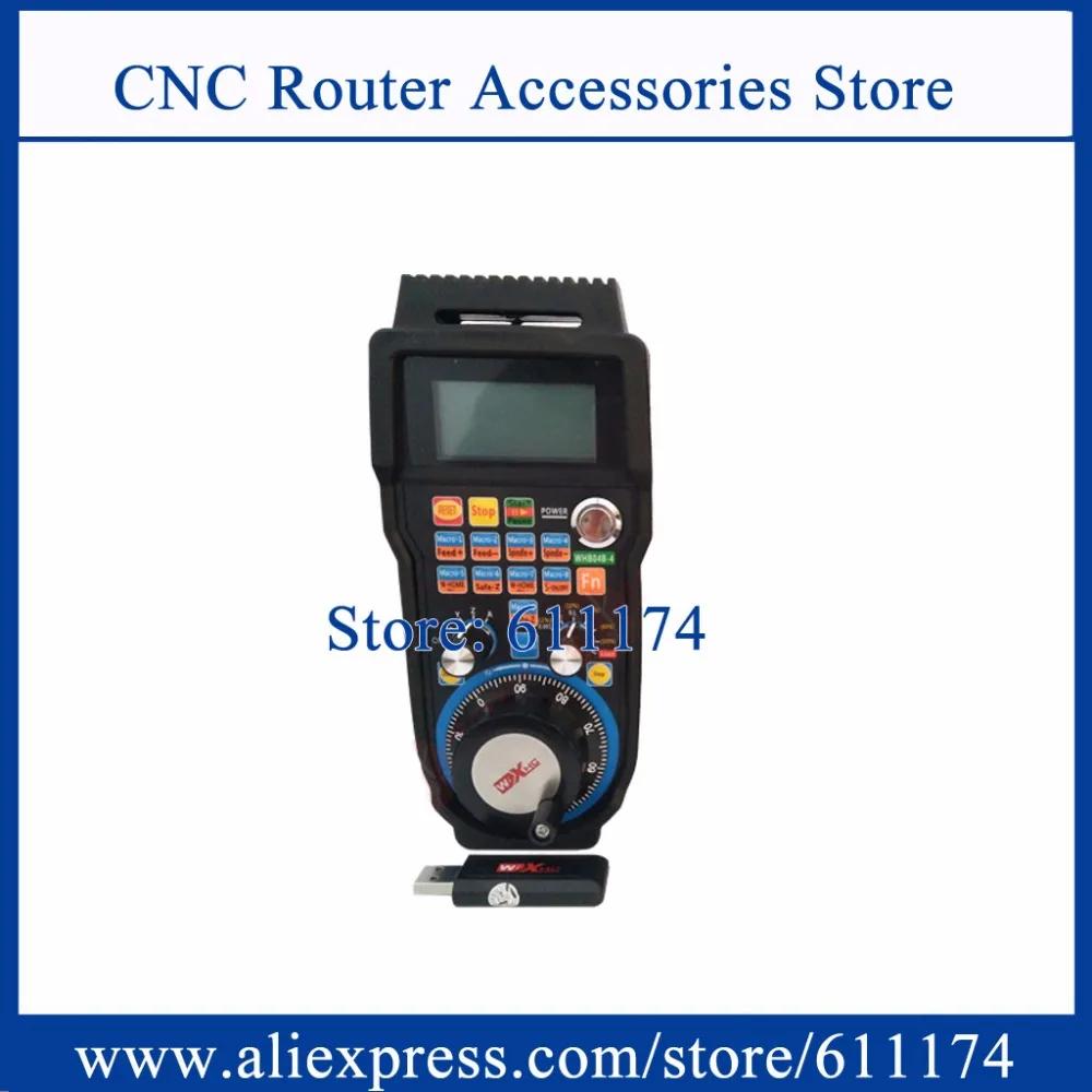
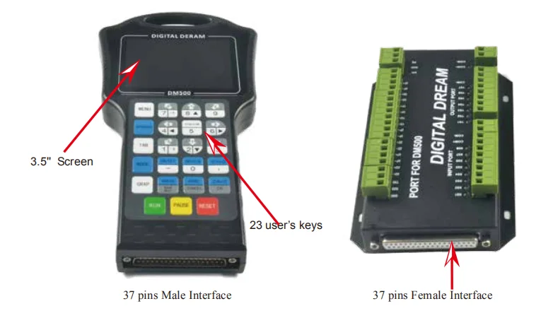
The DM500 motion controller contains the handheld motion controller,circuit switching wiring board,and
HDMI digital high-definition transmission cable.
The handheld motion controller and wiring board are communicated by 2 Meter 37 pins HDMI digital
high-definition transmission cable which is shielding twisted-pair cable to avoid interference.
The wiring board can be installed by DIN linearguide ways No. C45.

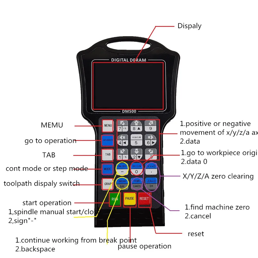
The front panel consists of 23 user keys and the 3.5’’ (480*320 ) LCD.
Explanation of Abbreviations
When operating the DM500 Controller, the users will come across some English abbreviations. Here a list
with explanations
FRO: Feed Rate Override
SRO: Spindle Rate Override
SRJ: Jog Speed Setting
F: Feed rate, unit is mm/min
S: Spindle Speed, unit rev/min.
X: The coordinate code of the X axis.
Y: The coordinate code of the Y axis.
Z: The coordinate code of the Z axis.
A: The coordinate code of the A axis
BUSY: The system is busy. You still can adjust FRO and SRO
READY: READY mode, any operation can be done
RESET: Reset mode, controller is in “OFF” mode, no operation can be performed
CONT: Continuous mode, each axis can be manually jogged with the arrow keys
Step :Manual Step Mode,each axis can be jogged in defined steps
MPG: MPG mode. Operate the machine with the MPG (Manual Pulse Generator)
AUTO: Run G code. Auto is showing when file is processing
Notes and Warnings
Keep away from exposure to moisture or water. This product contains sophisticated electronics
and must not get wet.
Wiring warning: the IO input terminal of this controller supports equipment with source power (such as
Inductive Proximity Switch ). When using this kind of equipment, pay attention to the polarity. Avoid the
+terminal to be connect with GND. This controllers has analog output for spindle control (0-10V). Please avoid
this terminal to ever connect with GND as damage to the controller may occur.
Operation warning. Please observe all security measures when operating the machine. The ESTOP
must be connected and properly labelled. In case of a problem, press the E-stop at once to avoid
damage to humans, animals and the equipment.
High voltage danger. The CR8-500 is connected to18-32V DC. Obey and follow the electricity safety
rules of your country when connecting this equipment.
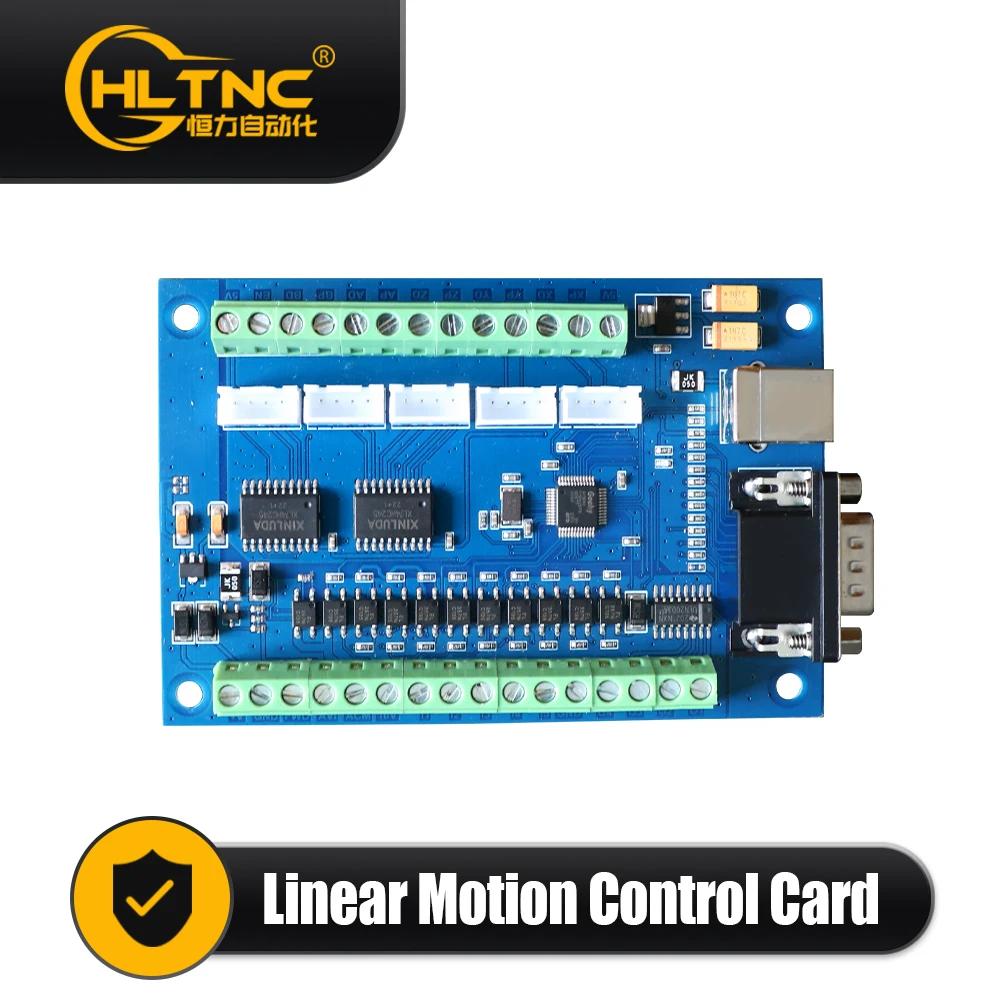
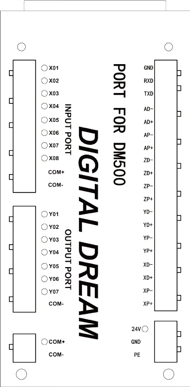
The Wiring Board Interface
Notice:
1. The users should prepare two power supply switch for each controller.One is for the controller
system,one is for the Inputs and Output ports.
2. 24V GND is the power supply for the controller,COM+ and COM- is the common terminal for Input
and Output ports.
3. The Low voltage for input signal is effective.By default it is the NPN switch.
4. The pulse and direction signal is differential output.
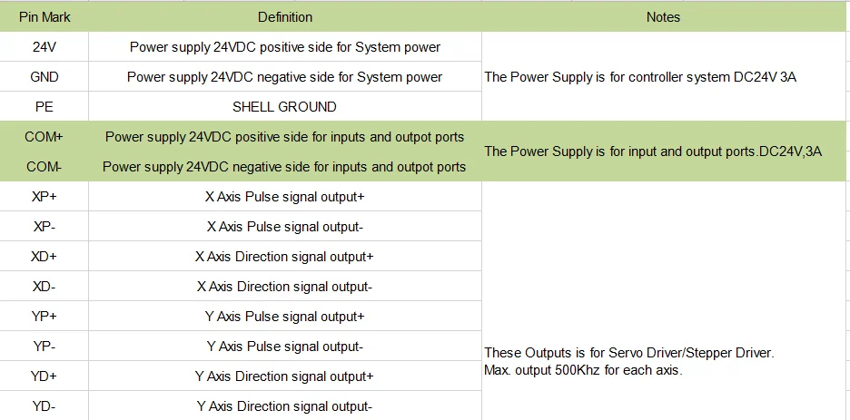
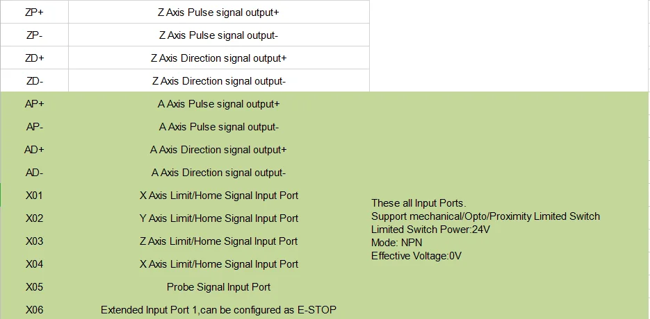
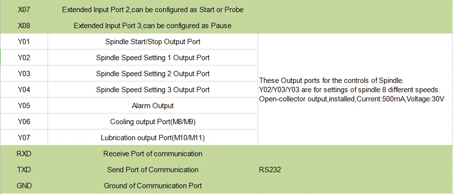
The Wiring Board Ports definition
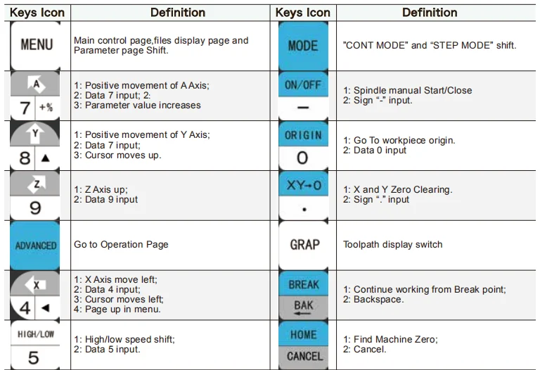
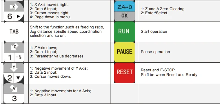
Definition of keys
Motion Controller System Description
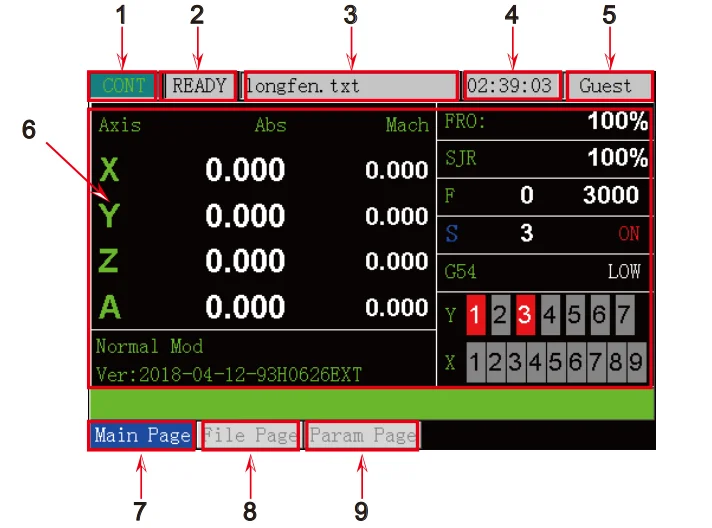
4.1 Main Page Description
1: Controller Current Mode
2: Controlller Working Status
3: Current machining file.(if the files name in red background color,means the controller cannot read the
U-disk)
4: Total working time
5: Current operation Rights
6: The information page
7: Main Page
8: File Page
9: Parameter Page
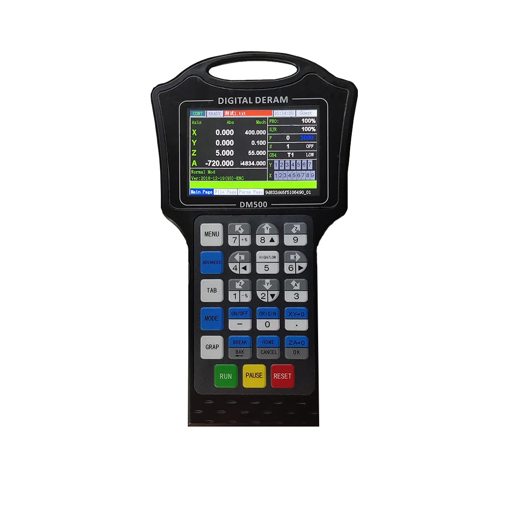
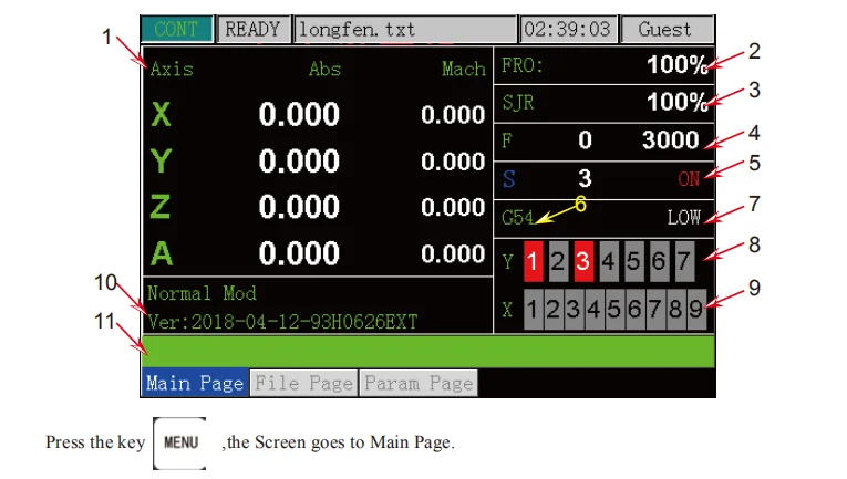
Main Page Description
Page description of Main Page
The Page discription:
1. Coordinate display: Here you can see the absolute coordinate and mechanical coordinate;
2. FRO: FRO controls the Feed Speed. The range is 0%-300%,”+%” and “-%” adjust the speed in 10%
increments;
3. SJR: SJR controls the jogging of the machine;
When in Cont Mode, ”+%” and “-%” can adjust the speed in 10% increments;
When in Step Mode, ”+%” and “-%” can change from 0.01mm to 0.1mm to 1mm and to 10mm;
4. F: F is the Feeding Speed.It shows the current machining speed;It shows the fixed feeding speed;
5. S: S is the spindle speed.It shows the current spindle speed;It also display the spindle status of
STOP/START;
6. Current workpiece Coordination: G54/G55/G56/G57/G58/G59 workpiece coordination;Mach Coordi�nation;
7. Manually High/low speed;
8. Output signal status;
9. Input signal status;
10. Version information and Programming date;
11. Machining information: G code information when automatically machining;Errors.
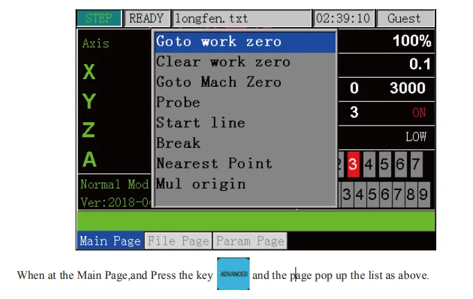
The Operation of Main Page


 배송기간
배송기간