|
Packaging Details - Unit Type: piece
- Package Weight: 0.3kg (0.66lb.)
- Package Size: 15cm x 15cm x 15cm (5.91in x 5.91in x 5.91in)
Packaging Details - Unit Type: piece
- Package Weight: 0.3kg (0.66lb.)
- Package Size: 15cm x 15cm x 15cm (5.91in x 5.91in x 5.91in)
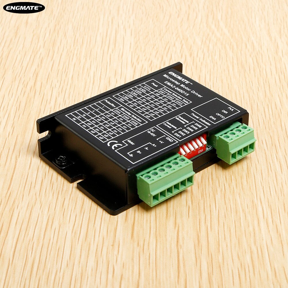
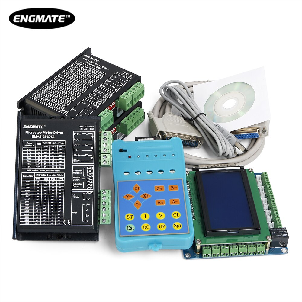
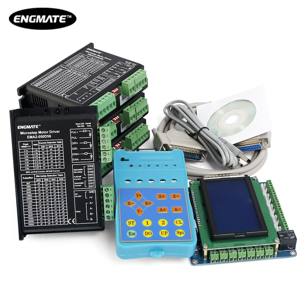
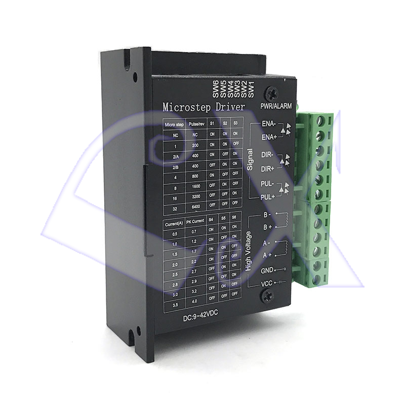
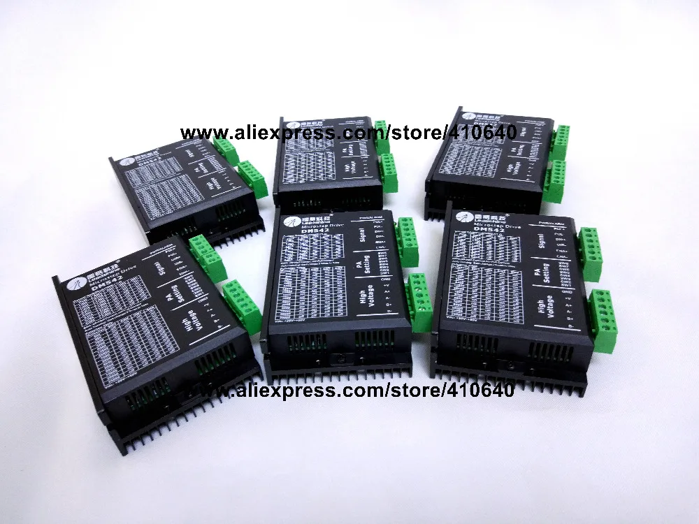
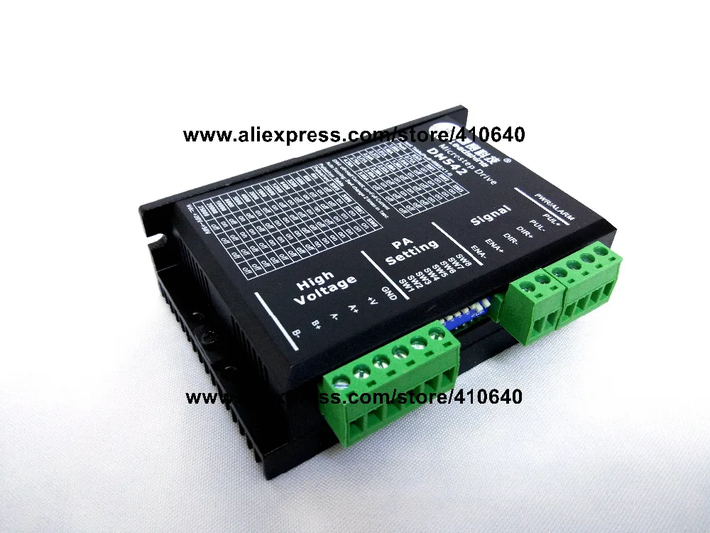
cellpadding="0" cellspacing="0" border="0" style="color:#111112;background-color:#000000;clear:both;;">  | | | | | | | | | | | | | | Notice: We only supply !!!Genuine!! DM542 2-Phase DSP Digital Stepper Drive The DM542 stepper drive adopts advanced features like electrical damping, anti-resonance, start-up smoothing, multi-stepping... With the input voltage of 20 - 40 VDC and output current of 1 - 4.20 A, it is capable of driving a wide range of 2-phase stepper motors with high precision at extra smoothness, quietness, and very low motor heating. Its multi-Stepping feature allows a low resolution step input to produce a much higher microstep output for smoother & quiet motor movement, and much lower motor heating. This feature will significantly improve the performance of your stepper control systems. | | DM542 | | Output current | Min | 1A | | Max | 4.2 (3.0 RMS)A | | Supply voltage | Min | +20VDC | | Max | +50VDC | | Logic signal current | Min | 7mA | | Max | 16mA | | Pulse input frequency | Min | 0kHz | | Max | 300kHz | | Isolation resistance | Min | 500M ohms | | Max | - | | Operating Environment | Working Temprature | 70 degree Max | | Ambient Temperature | 0-50 degree | | Cooling | - | Natural Cooling or Forced cooling |
| | Details | | | Pulse signal: In single pulse (pulse/direction) mode, this input represents pulse signal, each rising or falling edge active (software configurable);4-5V when PUL-HIGH, 0-0.5V when PUL-LOW. In double pulse mode (pulse/pulse) , this input represents clockwise (CW) pulse,active both at high level and low level (software configurable). For reliable response, pulse width should be longer than 2.5 us. Series connect resistors for current-limiting when +12V or +24V used. The same as DIR and ENA signals. | | | DIR signal: In single-pulse mode, this signal has low/high voltage levels, representing two directions of motor rotation; in double-pulse mode (software configurable), this signal is counter-clock (CCW) pulse,active both at high level and low level (software configurable). For reliable motion response, DIR signal should be ahead of PUL signal by 5 us at least. 4-5V when DIR-HIGH, 0-0.5V when DIR-LOW. Please note that rotation direction is also related to motor-driver wiring match. Exchanging the connection of two wires for a coil to the driver will reverse motion direction. | | | Enable signal: This signal is used for enabling/disabling the driver. High level (NPN control signal, PNP and Differential control signals are on the contrary, namely Low level for enabling.) for enabling the driver and low level for disabling the driver. Usually left UNCONNECTED (ENABLED). |
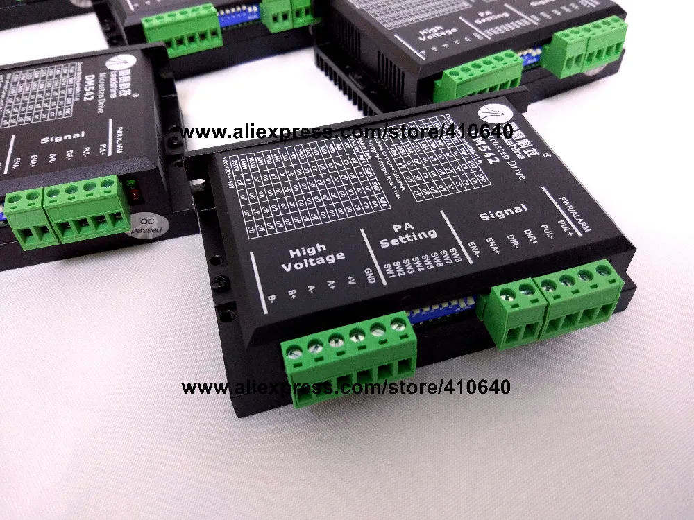
P2 : | Pin Function | Details | | GND | Power Ground | | +Vdc | Power supply, 20~50 VDC, Including voltage fluctuation and EMF voltage. | | A+, A- | Motor Phase A | | B+, B- | Motor Phase B |
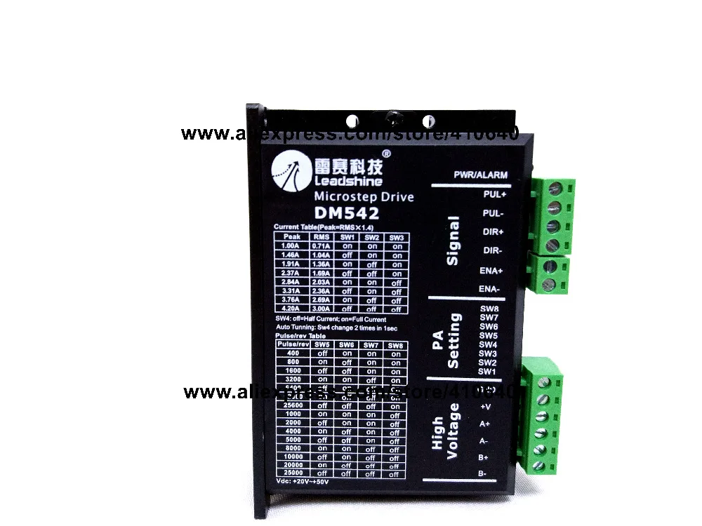
Resolution & Current Selection: Microstep resolution is set by SW5, 6, 7, 8 of the DIP switch as shown in the following table: | | SW5 | SW6 | SW7 | SW8 | | Default/Software configured, (From 200 to 102,400) | ON | ON | ON | ON | | 400 | OFF | ON | ON | ON | | 800 | ON | OFF | ON | ON | | 1600 | OFF | OFF | ON | ON | | 3200 | ON | ON | OFF | ON | | 6400 | OFF | ON | OFF | ON | | 12800 | ON | OFF | OFF | ON | | 25600 | OFF | OFF | OFF | ON | | 1000 | ON | ON | ON | OFF | | 2000 | OFF | ON | ON | OFF | | 4000 | ON | OFF | ON | OFF | | 5000 | OFF | OFF | ON | OFF | | 8000 | ON | ON | OFF | OFF | | 10000 | OFF | ON | OFF | OFF | | 20000 | ON | OFF | OFF | OFF | | 25000 | OFF | OFF | OFF | OFF |
The first three bits (SW1, 2, 3) of the DIP switch are used to set the dynamic current: | Peak Current | RMS Current | SW1 | SW2 | SW3 | | Default/Software configured (0.5 to 4.2A) | ON | ON | ON | | 1.46A | 1.04A | OFF | ON | ON | | 1.91A | 1.36A | ON | OFF | ON | | 2.37A | 1.69A | OFF | OFF | ON | | 2.84A | 2.03A | ON | ON | OFF | | 3.31A | 2.36A | OFF | ON | OFF | | 3.76A | 2.69A | ON | OFF | OFF | | 4.20A | 3.00A | OFF | OFF | OFF |
|


 배송기간
배송기간